Student Corner 9: Funnel – A Simple Device, Which Has A Lot Of Applications
Editor | On 29, Sep 2006
By: Abram Teplitskiy
A funnel is a conically shaped pipe, employed as a device to channel liquid or fine-grained substances into containers with a small opening. Most people first saw a funnel in their kitchen, where it was used widelly in preparing food, including our favorite biscuits. The diameter of the spout of a regular kitchen funnel is about 1/10 that of the upper bowl. The almost cylindrical tube below the conical upper part that opens into the spout can vary in length. You can see a general look of a funnel in the picture below.
Courtesy of GEE Consultants, Inc. Dallas, TX
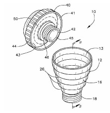
Most readers know a soft cookie filled with fig jam. James Henry Mitchell invented a special machine in 1891 for mass production of Fig Newtons Cookies.This machine worked like a funnel within a funnel; the inside funnel supplied jam, while the outside funnel pumped out the dough, this produced an endless length of filled cookie, that was then cut into smaller pieces. The Kennedy Biscuit Works used Mitchell’s invention to mass-produce the first Fig Newton Cookies in 1891. Let’s take a moment and become aquantained with the design of a more contemprorary two-funnel system, which has a title “Easy-Flow-Funnelâ€, which was proposed in United States Patent # 6119739. General look of such two-funnel system is shown in Fig. 2.
Public Domain – US Patent # 6119739
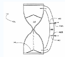
We can call the above-shown two-funnel system a funnel assembly, which includes an interior funnel and an exterior funnel. When an interior funnel is inserted into the exterior funnel, three equally spaced raised projections prevent contact between the outer surface of the interior funnel and the inner surface of the exterior funnel. This arrangement creates air passages between the two funnels for the venting of displaced air. Consequently, the liquid being poured runs faster into a container, unaffected by the upward movement of the vented air. The interior and exterior funnels are individually, integrally formed and come together as the exterior funnel is snapped into place next to the interior funnel by three wedges protruding on the outside spout of the interior funnel. These wedges are forced against the spout of the exterior funnel and hold the two funnels equidistant to each other. In the next picture readers can see that two funnels, connected vertically with narrow end could fulfill “dutes†of hour-glasses, as shown in next picture.
Public Domain – US Patent # 6,260,996
Hourglass, shown in Fig.3, comprise a first reservoir transfer end, the transfer end being smaller than the collecting end; a necked duct extending between the transfer end of said first reservoir and the transfer end of said second reservoir, the necked portion providing a restricted fixed flow path between the first reservoir and the second reservoir; and a bypass duct extending between the collecting end of said first reservoir and the collecting end of said second reservoir, the bypass duct having a valve that allows capture of an amount of material used to measure time with the hour-glass.
Funnels are usually made of either stainless sheet metal, or plastic, but sometimes-disposable paper funnels are used in cases where it would be difficult to adequately clean the funnel afterwards (for example, in adding motor oil to a car). Dropper funnels, also called dropping funnels or tap funnels, have a tap to allow the controlled release of a liquid. The term “funnel” is sometimes used to refer to the chimney or smokestack on a steam locomotive. There is also a type of spider known as a funnel-web due to its habit of building its web in the shape of a funnel.
Effect of funneling or, in other words, concentrating by funnel-like shape could be applied not only to directing flow of liquids, gases or sand-like materials, but even to concentrating light in fiber-optic devices.
What do you think the problems, that can be solved, by a funnel in a Soil Laboratory? For example, density of a liquid mixed with clay soil particles usually measured by a Hydrometer – a glass cylindrical tube with a weight in bottom. Inserted vertically, the Hydrometer according to Archimedes Law would immerse in the liquid’s depth depending on the density of liquid, as shown in the following picture.

Courtesy of GEE Consultants, Inc.
Looking at this picture 4-a, you can see the problem – manually centering Hydrometer could influence the accuracy of the results of the mesurement. So, we need a method to help automatically center a Hydrometer inside the cylinder. To see what could happen by chance, take a look at the funnel. We are sure that you’ll exclaim “Eurica!â€, because you’ll for sure get an idea to put a Hydromrter in a glass cylinder through a funnel!
Look at the picture 4-b, and you’ll see a very simple solution to this problem – inserting a funnel atop the cylinder would stabilize the Hydrometer lowing in the Cylinder. You can see that drops of water are falling vertically. A funnel solved the problem! Such a simple structure as funnel could help people with a lot of other problems. Now, please, answer a question, can funnel help in knitting? If you have doubt that such question has sense, look on the picture below. A 5-year old Bushra Firdows Rahman shows how usage of the funnel helps to prevent yarn from meshing.

Courtesy of Motiar and Sahana Ruhman
How to apply funnel principle in diving is shown in Fig. 6. A diving bell having a first funnel-shaped member, which has a cone-shaped portion with a cylindrical portion projecting from an apex-most portion of the cone-shaped portion. A lid for sealing and unsealing egress and passage of air and water through opposite ends of the cylindrical portion of the first funnel-shaped member.
Public Domain – US Patent
A second funnel shaped member having a cone-shaped portion with a cylindrical portion projects from an apex most portion of the cone shaped portion. The second funnel shaped member being held about the first funnel shaped member with a space between the first and second funnel shaped members for receiving sand or the like.
Can you a priory estimate of advantages of telescoping funnel? We are sure that readers can do this estimation. First of all, the telescoping funnel could be in two positions – for transportation, when it is compressed, and in working – funneling liquids, granulating or like materials. This telescoping funnel was developed in US Patent #6,397,907 and shown in Fig. 7. A telescoping funnel apparatus includes a funnel that includes an open top extending into a channel.
The channel extends through an open bottom of the funnel allowing fluid to be directed through the funnel. The open top and bottom of the funnel has common longitudinal axis. A cover is provided for selectively closing the open top of the funnel.

Public Domain – US Patent #6,397,907
The funnel principle along with principles of hydraulic can effectively be applied in systems for catching and transporting fish. One of such systems was proposed and patented by American Inventor H. Gernsback at September 20, 1955 in USA. This system utilizes flow of water to entrap and to transport the fish. Basically the invention involves the provision of a funnel shaped collector submerged in fish containing waters, possibly miles from shore, and connected by a fish conveying water pipeline to suction pumps on shore and operating to create an inflow into the mouth of the funnel and flow of water and entrapped fish through the pipeline to a suitable fish processing station on shore, and to vegetable and chemical extracting plants for removing other valuable materials from the water. The principle part of this invention is illustrated below in Fig.8. Interested future inventors can find details of this patent in US Patent Database.

Public Domain – US Patent # 2,718,083
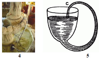
Below readers could see a fountain from a ranch in Lucas, TX. This fountain contains hydraulic elements, which were named by one of the great English scientist of 15 Century – Robert Boyle. The sketch of this hydraulic miracle is shown in the same row with fountains.

And it’s Application in Fountain
Courtesy of First Lady of Lucas, TX Jennifer Sanders
1,2,3,4 – looks of Fountains with Boyle Siphon, 5-Scetch of Boyle Siphon.
elements. If you will analyze how this hydraulic system works, you’ll conclude that water, which flows out from fountain, through a siphon device returns back to fountain due to forces acting in siphon. We’ll devote special attention to the siphon one of ours Student’s Corners. We’ll ask our members provide some historical searches and find out the history of Funnel and Siphon. Such search could be a great historical adventure.
Materials for the Student’s Corner #9 are prepared by a Team of Enthusiasts under Leadership of Dr. Abram Teplitskiy (Dallas, TX) and First Lady Jennifer Sanders (Lucas, TX).
Happy Inventing.


