Using Substance-Field Model to Make Concept Design for a Clamping Device
Editor | On 05, Nov 2005
By: Jen-Yu Liu, Hsin-Sheng Lee
Jen-Yu Liu1 and Hsin-Sheng Lee
Department of Power Mechanical Engineering
National Formosa University
64 Wun Hua Road, Huwei, Yunlin 63208, Taiwan.
E-mail: jennifer@nfu.edu.tw(Corresponding author)
Abstract
The main subject of this paper is optical fiber connector-grinding machine’s clamping device. We use TRIZ as the innovative concept design theory, make Innovation Situation Questionnaire analysis of current clamping devices, establish a linkage diagram of cause-effect relationship, formulize problem descriptions, simplify the function model, construct Substance-Field model, make system design analysis, and develop a complete and effective system for clamping devices from seventy-six standard solutions, and then lastly propose an innovative design plan for the clamping device. The innovative clamping device can hold 25% more connectors compared with the original clamping device, and the detaching and assembling time will be reduced. The research findings can provide references for the design of clamping devices of the optical fiber connector-grinding machines, and can also be useful for developing a supplementary teaching material for creative engineering design courses.
1. Introduction
Optical fiber features high bandwidth, low loss, small size, and is free from electromagnetic interference. Therefore, it is used as the main component in communication networks [1-2] , optical fiber connector is mainly used for component connection in the optical fiber communication system. Optical fiber manufacturers usually provide diversified optical fiber connectors for customers to select, at the same time, they also provide optical fiber connectors with customized specifications and designs [3] . Figure 1 shows a common optical fiber connector, the extruded part at the front is covered with optical fiber. The diameter of the optical fiber terminal face is 2 mm and the length of it is 4 mm; the ferrule sleeve has two layers: the inner sleeve and outer sleeve, the diameter of the inner sleeve is 6 mm, the diameter of the outer sleeve is 10 mm, the rear end of the connector is covered by a plastic layer to protect the optical fiber.
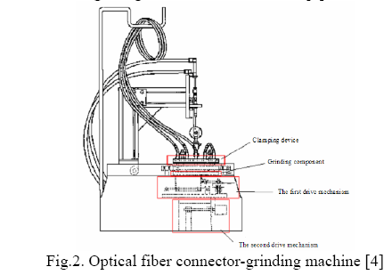
The terminal face of the optical fiber connector should be smooth, so that light can smoothly pass through the connection to transmit signals; therefore it is necessary to use a dedicated grinding machine to grind the terminal face of the optical fiber connector [2] in order to make it smooth. Figure 2 shows the dedicated grinding machine used to grind the terminal face of the optical fiber connector. It consists of a clamping device, grinding component, the first drive mechanism and the second drive mechanism etc. The clamping device is used to clamp the optical fiber connector, the grinding component is used to grind the terminal face of the optical fiber, the first drive mechanism is used to drive the grinding component to move along the figure-8 motion trajectory, and the second drive mechanism is used to drive the grinding component to move along straight lines at the same time [4] .
Some research literature on the clamping devices of optical fiber connector-grinding machines, such as those made by Lin et al. [5] , suggested that the two sides of the hole on the clamping disc used to hold the optical fiber connector can be designed into two different semicircles, as shown in Figure 3. Through left-right translation between upper and lower pressing plates, the optical fiber connector is pushed into the proper hole. The advantage of this design: It can hold optical fiber connectors of different shapes, has simple structure, and it can grind 25 optical fiber connectors at one time. The clamping device design by Hong [6] can assemble several clamps onto the clamping disc, as shown in Figure 4. The advantage of this design: It can quickly clamp the optical fiber connector, increase productivity and enhance market competitiveness. However, the clamps occupy a large area on the clamping disc, so the number of clamps is limited, therefore it will grind a smaller number of optical fiber connectors, and its structure is complicated.
As optical fiber connectors are cheap, generally people make profit from high output. Therefore, the number of optical fiber connectors that can be ground at one time is an important factor that must be considered when designing and innovating the clamping devices of optical fiber connector-grinding machines. The innovative clamping device design must meet the following requirements: (1) The number of optical fiber connectors that can be clamped at one time should be more than the number that can be clamped by a current clamping device; (2) It is possible to quickly install and detach optical fiber connectors onto and from clamping device precisely; (3) Should not increase the complexity of the mechanism.
This paper uses Altshuller’s TRIZ theory (Theory of Inventive Problem Solving)[7] as the basis for innovative concept design of optical fiber connector clamping device. Firstly, this paper make an ISQ (Innovation Situation Questionnaire) analysis of the current clamping devices, establish a linkage diagram of cause-effect relationship, formulize the problems to be improved, simplify its function model, construct substance-field model for the clamping device, and develop a complete and effective substance-field model for the clamping device from the seventy-six standard solutions. Then it will propose an innovative design plan for the clamping device, and use the CAD software CATIA to design solid models of the innovative clamping device and simulate the motion of the device so as to verify the feasibility of the innovative clamping device. The research findings can provide references to the design of innovative clamping devices of optical fiber connector-grinding machines, make actual contributions to optical fiber grinding machine manufacturing industry, and can also be useful for developing a supplementary teaching material for creative mechanism design courses.
2. TRIZ theory analysis
This paper takes the clamping device designed by Hsieh et al. [4] as the original mechanism to make an innovative concept design of the clamping device of the optical fiber connector-grinding machine.
2-1 Analysis of Innovation Situation Questionnaire (ISQ)
According to the ISQ analysis, this system is named as “optical fiber connector clamping deviceâ€; the main useful function of the system is to clamp and fix optical fiber connectors, and ensure that the terminal face of each optical fiber is perpendicular to the grinding disc and smoothly contacts with the grinding component during grinding. The clamping device of the original optical fiber connector-grinding machine consists of the grinding disc seat, grinding disc bottom plate, four support bars, grinding-disc pressing plate, and four bolts, as shown in Figure 5. Working principle: To carry out clamping, put the optical fiber connector to the grinding disc pressing plate, move the grinding disc pressing plate so that the connectors are sucked into the inserting holes, lock the fixing bolt, fix the grinding disc pressing plate and the grinding disc seat. After all of the previous are done, grinding can be started.
The system’s function resource consists of the clamping of an optical fiber connector to the clamping disc, its field resource consists of the pressure of the clamper, mechanical motion and grinding, the affect of the heat generated through grinding to the optical fiber terminal face. Its information resource consists of the control of the air pressure. Its space resource consists of the position of the clamping disc on the grinding machine and the space used to hold the clampers on the clamping disc. Its time resource consists of the need for holding more optical fiber connectors at one time in order to save time.
The original clamping device can hold twenty-four optical fiber connectors at one time. If the innovative clamping device can hold more optical fiber connectors while keeping the same clamping function as the original clamping device, the purpose of the innovative design will be realized. According to the aforementioned ISQ analysis, we can conclude the requirements for innovative design of the optical fiber connector clamping device are as following:
(1) Increase the number of optical fiber connectors to be clamped;
(2) The upper and lower clamp plates of the clamping device can be quickly detached;
(3) The structure of the device must be simple so as to reduce cost.
2-2 Problem Formulation (PF) (Reference 7)
The main function of the optical fiber connector-clamping device is to provide enough clamping force in order to tightly clamp and fix the optical fiber connectors, so that the terminal face of the optical fiber can be smoothly and stably ground along the preset track on the grinding machine. This paper will start from the useful function—clamping to establish a linkage diagram of cause-effect relationship, as shown in Figure 6. The node 1 in the linkage diagram – can provide useful clamping function to node 2 – in order to reduce the offset caused by insufficient clamping force (the necessary force needed to keep the connector in perpendicular attitude).
When the connector is kept in perpendicular attitude, the node 3 can obtain a good processing face; node 1 – having useful clamping function – will provide clamping force by the upper and lower clamping plates at node 4. However, if the upper and lower clamping plates at node 4 give too much acting force, the optical fiber connector at node 5 will be deformed which is a harmful function; the acting force upper and lower clamping plates at node 4 is provided by the fixing of bolts (which apply force to the upper and lower clamping plates) at node 6; the force applied by the bolts to the upper and lower clamping plates is provided by the locking force of the screw at node 7; the locking force of the screw at node 7 can be used to eliminate the harmful function of the unstableness of the optical fiber connector at node 8; the locking force of the screw at node 7 is provided by the mechanical locking function at node 9; the mechanical locking function at node 9 will cause two kinds of harmful functions: the time consuming work procedures at node 10 and the manual operation at node 11; the manual operation at node 11 will reduce the processing efficiency at node 12. In figure 6, the circle represents the useful function, and the rectangle represents the harmful function. The cause-effect relationship between different functions: The arrowed line means that this function will satisfy the other function; the bold line means this function may cause other harmful functions; the cross black line means this function can eliminate other harmful functions.
2-3 System simplification analysis
Computer-aided innovative design software TechOptimizer based on science and technology, integrated TRIZ’s theory and established a knowledge base for invention and application. It is widely used in industries, and is an indispensable tool for engineers. TechOptimize’s trimming technique can increase value of the system. The trimming technique deems that if a component has a low value, it is better to discard it rather than modify it, therefore, the trimming technique can simplify the original function model. The use of the trimming technique has the following advantages:
(1) If operations or components are deleted, the related harmful functions will be deleted as well;
(2) If operations or components are deleted, process or product cost will be reduced;
(3) If operations are deleted, the functions will be simplified;
(4) If conditions or components are deleted, the useful functions will be redistributed;
(5) If the useful functions are deleted, the useful functions should be transferred to other operations or non-processed components.
TRIZ theory deems that an ideal machine should be still functional even if its component does not exist. From the view of an innovative strategy, the more operations or components you delete, the higher the innovative level, and the innovation will be more likely to make a breakthrough.
2-3-1 Calculate value
Value calculation is an important step in the trimming technique, and the value decides the sequence order of the possible simplified components or operations. According to the calculation criterion for TechOptimizer value, to calculate the value of a component, the function, problem and cost of that component must be quantified. In the TechOptimizer product analysis module, the numerical value of the function is decided by the function rank; the numerical value of the problem is decided by the problem significance; the cost indicates the cost of the whole product life-cycle, the numerical value is decided by the cost rank. After the function, the problem and the cost are quantified, and we can use the product analysis module defined value to calculate the value.
2-3-2 Simplification Procedures
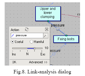
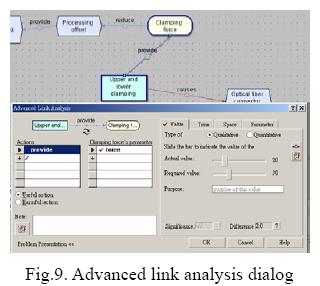
To make product analysis with the trimming technique,it is necessary to establish a function model, and then begin the trimming technique. The trimming technique of the product analysis module consists of the following procedures: (1) component evaluation; (2) integrated component evaluation; (3) trimming condition. According to the linkage shown in Figure 6, this paper establishes the function model and evaluating condition of the defined value, shown in Figure 7 ( represents component, represents super-system, represents product). We define function value of components of “upper and lower clamping plates†and “fixing boltsâ€, the link-analysis dialog as shown in Figure 8; define problem rank of “upper and lower clamping plates†and “clamping forceâ€, the advanced link analysis dialog as shown in Figure 9, key in each component’s cost value, and calculate each component’s value.
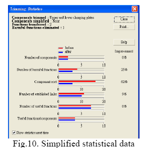
In order to avoid deforming the optical fiber connector, we delete the upper and lower pressing plates, and select a new component (similar pin socket of central processing unit) to increase the system value. The simplified statistical data is shown in Figure 10; the simplified function model is shown in Figure 11 (the gray line represents a deleted component, the bold line represents the simplified useful function).
2-4 Simple complete Substance–Field model grammar
Substance–Field model analysis tool can use innovative problems to form an analysis model related to the current technical system, and this tool is often used to improve the places where the defects of the current system exist. The basic components that make up a complete substance-field model are two substances ( 1 S , 2 S ) and one field (F), this is a triangle model, as shown in Figure 12. The “Substance†indicates the system, sub-system, a single object, or indicates component or function. “Field†generally indicates a sort of energy, which is used to provide energy, power, or react to maintain a certain effect. A simple complete Substance-Field model is an expected function output by an object or a substance ( 1 S ), resulted by another object or substance ( 2 S ) through the reaction of some method (energy, F). In other words, 1 S is the receiver of the action, 2 S uses the energy resource in the 1 S method.
Substance–Field model analysis has four basic models:
(1) incomplete system which needs to be completed into a new effective complete system;
(2) effective complete system which is the final system to be completed in the Substance–Field model analysis;
(3) ineffective complete system which should be improved to produce the expected effect;
(4) harmful complete system, the negative effect of the system should be eliminated in order to form a new effective system.
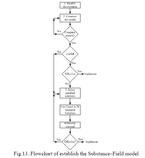
The key of the Substance–Field model analysis is to analyze the model consisting of the current system and find out which of the four kinds of models it belongs to, and then consult the TRIZ theory to find out the most suitable innovation scheme for the current system from the seventy-six standard solutions [9] provided by the four kinds of Substance-Field models. This paper establishes the Substance–Field model in terms of the flowchart in Figure 13.
On the basis of the useful and harmful functions in the linkage diagram (Figure 6) and the flow for establishing the Substance–Field model (Figure 13), this system’s Substance–Field model is established by the following procedures:
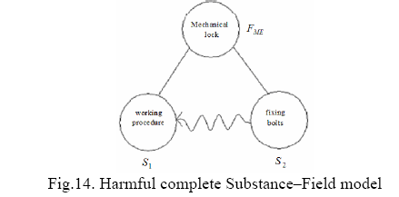
(1) Select the node 6, 9, 10 in the linkage diagram to establish a Substance–Field model. Substance 1( 1 S ) is the time consumption work procedure at node 10, Substance 2( 2 S ) is the fixing bolt at node 6, and the mechanical lock at node 9 is the mechanical field ( ME F ).
(2) The clamping device uses the fixing bolts to fix the optical fiber connectors, but this will cause a time consumption work procedure. Therefore, step one form a harmful complete Substance–Field model, as shown in Figure 14. The line in the Figure represents the useful function, represents the harmful function.
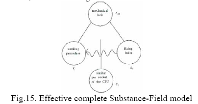
(3) As to the harmful complete Substance–Field model, TRIZ suggests five methods to eliminate the negative effect of the harmful complete Substance–Field model, and make it into an effective complete system: (a) Eliminating harmful interaction by introducing 3 S ; (b) Eliminating harmful interaction by introducing modified 1 S and/or 2 S ; (c) Drawing off a harmful action; (d) Counteracting a harmful action with 2 F ; (e) Switching off a magnetic influence [9, pp.134-138 ] .This paper adopts method (a), makes reference to the operational principle of central processing unit (CPU) installation, introduces another substance 3 S as the similar pin socket of the CPU, and makes the current model into a effective complete Substance-Field model, as shown in Figure 15.
3. Development Solution
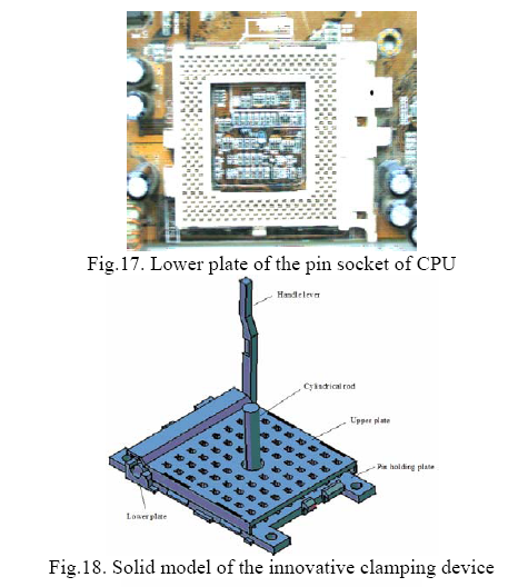
The procedure to stall a CPU is as follows: Insert the CPU onto the upper plate of the soleplate, turn the handle lever to move the upper and lower plates in the opposite direction, and then move the pins of the CPU into the positioning hole on the lower plate. Next, push down the handle lever so that the pins of the CPU can be tightly inserted into the position. The upper plate of the pin socket of CPU is shown in Figure 16; the lower plate of the pin socket is shown in Figure 17. The innovative concept of the clamping device in this paper is to make use of the working principle similar to the installation of the CPU to redesign the shapes of the upper and lower plates, make the clamping device into a structure similar to the structure of the pin socket of the CPU, and use the handle lever to make simple rotation movement, thus the clamping of optical fiber connectors is completed. The clamping device innovative design consists of three parts: the upper plate, the lower plate and the handle lever. The solid model of the innovative clamping device is shown in Figure 18; the exploded assembly drawing of the clamping device is shown in Figure 19.
The lower plate of the optical fiber connector-clamping device is shown in Figure 20, the optical connectors are inserted into the orifice plate with an inserted length of 270 mm, with a width of 250 mm, and the plate thickness is 15 mm. The diameter of each inserting hole is 10 mm. There are altogether 60 inserting holes for jumper wires. Thus the number of optical fiber connectors is increased by 25 percent from forty-eight connectors in the original device. There are 4 extruded locating pin holding plates, each holding plate is 50 mm long and 40 mm wide, in the central position, there is a locating pin hole with a diameter of 20 mm, with which the lower plate of the clamping device can be conveniently fixed on the stand of the optical fiber grinding machine. The groove used to hold the eccentric circular handle lever is 250 mm long and 35 mm wide, the shape of the groove should be designed according to the external shape of the eccentric circular lever, and the groove should be designed to contact closely with the eccentric circular lever. In the center of the lower plate, there is installed a 30 mm-long cylindrical rod, which is used to connect the suspending device of the grinding machine. After the optical fiber connectors are inserted into the holes, the optical fibers should extend out from the lower plate by more than 3 mm, as shown in Figure 21.
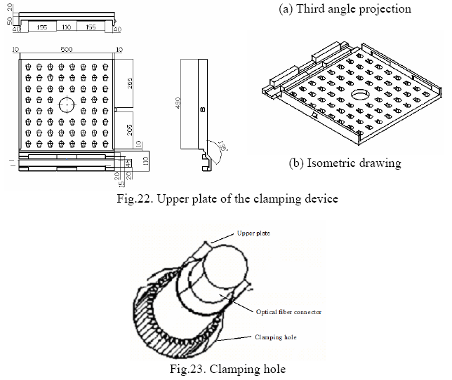
The upper plate of the optical fiber connector-clamping device is shown in Figure 22. It is 305 mm long, 260 mm wide and 35 mm thick. In order to enable the long cylindrical rod on the lower plate to pass through the upper plate, there is a round hole with a diameter of 50 mm at the center of the upper plate. Around this round hole, there are 60 optical fiber connector inserting holes, each inserting hole consists of a small circular shape and a small square shape. The area covered by the 60 optical fiber connector inserting holes is 260 mm x 260 mm. After the optical fiber connectors are inserted, when you push down the handle lever to drive the upper and lower plates to carry out translational motion, the square holes will push the optical fiber connectors into the clearance between the upper and lower plates, so that the optical fiber connectors will be fixed, as shown in Figure 23. The external shape of the eccentric circular handle lever between the upper and lower plates is shown in Figure 24, the eccentric circular part of the handle lever is 275 mm long, the handgrip part is 285 mm long, the eccentric circle consists of an ex-circle rod and a small eccentric circular rod. When the handgrip is rotated, the eccentric part of the eccentric circle will cause a translational motion between the upper and lower plates, and the translational motion will push the upper and lower plates of the clamping device to carry out an oppositional translational motion between them.
The advantage of the design principle of this innovative device is that the operator can simply put the optical fiber connectors to the ground into the holes along the upper plate of the clamping device, and then rotate the eccentric handle lever, and thus these optical fiber connectors can be fixed. After grinding is completed, nothing remains but to pull up the handle lever so that the upper plate returns to the original position. Then the optical fiber connectors can be easily taken out.
4. Conclusion
On the basis of TRIZ method, this paper makes ISQ analysis of problems to be improved in the current optical fiber connector clamping device, draws a cause-effect relationship linkage diagram, under the principle of formularized description. Furthermore, it describes the problems to be improved through formularized method, simplifies the function model, and makes Substance-Field analysis. It consults the pin socket mechanism of the computer CPU, makes innovative designs of the new optical fiber connector clamping device. The innovative clamping device not only keeps the same clamping function as the original one, but also can be quickly detached, and the number of optical fiber connectors held at one time is increased by more than 25%. The research findings not only can provide a design concept for optical fiber connector clamping device, make actual contributions to the optical fiber connector clamping device manufacturing industry, but can also be useful for developing a supplementary teaching material for creative engineering design courses. Performing prototype based on this will be developed in the future.
Acknowledgements
The authors would like to thank the National Science Council of Republic of China for financially supporting this research under Contract No. NSC 92-2522-S-150-003-X3.
References
[1] M.Y. Li, Introduction of Optical Fiber Communication, Ch-Wa Books Company, Taipei, 1992.
[2] C.S. Guo, “How The Optical Fiber Pass the Newsâ€,
http://www.hk-phy.org/iq/optical_fibre/optical_fibre.html, 2004.
[3] W.Y. Zhang, “Link Technology and Examination of Optical Fiberâ€, Opto News & Letters, Vol.89, pp.6-10, 2001.
[4] L.C. Hsieh, S.L. Chang, J.Y. Liu, and S.C. Chou, “Optical Fiber Grinderâ€, Taiwan Patent No. 431258, 2000.
[5] E.A. Lin, S.C. Chou, W.C. Xu, and W.Y. Zhang, “Optical Fiber Grinderâ€, Taiwan Patent No. 394125, 1999.
[6] C.H. Hong, “Improvement Structure of Optical Fiber Grinder Holder Plateâ€, Taiwan Patent No. 524162, 2001.
[7] J. Terninko, A. Zusman, and B. Zlotin, Systematic Innovation, St. Lucie Press, New York, 1998.
[8] TechOptimizer Training Course, Invention Machine Corporation, 2000.
[9] Tools of Classical TRIZ, Ideation International Inc., 1999.
[10] J. Terninko, “Su-Field Analysisâ€, The TRIZ Journal, pp.1-12, 2000/02.


