EMS Models: Adaptation Of Engineering Design Black-Box Models For Use In TRIZ
Editor | On 16, Apr 2005
Madara Ogot
Engineering Design Program, and
Department of Mechanical and Nuclear Engineering
The Pennsylvania State University
University Park, PA 16802, USA
madaraogot@psu.edu
Abstract
The Theory of Inventive Problem Solving (TRIZ) has been widely recognized as a powerful systematic innovation technique that can be applied to a wide arrange of disciplines. This paper focuses on engineering design and illustrates how modeling methods already familiar to engineering designers can be adapted for use in TRIZ. Specifically, the ‘black-box’ modeling technique, common in problem formulation and clarification in engineering design, is modified for use in TRIZ. The new technique, referred to as Energy, Material, System modeling, can not only serve as a substitute for substance-field modeling, but as it builds on existing knowledge in the engineering design community, removes one of the barriers to wider TRIZ adoption by not requiring designers to learn new and radically different modeling techniques. The efficacy of the technique is illustrated via several examples.
1. Introduction
TRIZ has been touted as a method that can be applied across numerous disciplines due to the generality of its collection of principles and tools. In trying to generate a wider audience, most TRIZ texts use the general modeling methods and terminology developed over the years by the TRIZ community. The presentations, however, may also present a barrier to wider implementation due to the difficulty in relating TRIZ concepts typically discussed in the context of TRIZ modeling techniques to one’s specific discipline.
Despite the power of TRIZ, it has not seen wide usage in the engineering design community, both in industry and in academe. This article explores ways to increase the implementation of TRIZ in the engineering design community by adapting and incorporating modeling techniques already familiar to engineering designers into TRIZ. This is achieved by adapting the black-box modeling technique, widely used in engineering design for problem clarification and decomposition, for use in TRIZ. The new technique, referred to as Energy- Material-Signal (EMS) modeling, can not only serve as a substitute for substance-field analysis, but also provide the following desirable features.
1. Builds on existing knowledge within the engineering design community, thereby removing one of the barriers to widespread TRIZ adoption.
2. Applicable to both physical and technical contradiction systems.
3. Inherently provides sequence of events within the modeled system.
4. Includes multiple scenarios in the same model.
5. Identifies the true problem to be solved, within the context of the overall system.
6. Includes all the resources available in the system that can be used to furnish a final solution. A separate resource list is therefore not required.
The development and use of the EMS model in the context of two examples follows in the rest of the paper. In addition, the standard solutions, most based on substance-field modeling, are modified to incorporate the new modeling method.
2. TRIZ
TRIZ, the Russian acronym for Theory of Inventive Problem Solving, was first developed in Russia by Genrich Altshuller and is now used across the world. It was originally based on analyses in the early sixties and seventies of thousands of Russian patents1. These original analyses articulated numerous solution patterns found across patents that can be successfully applied to solve new problems. These patterns have since been synthesized into numerous tools including (1) physical effects, (2) laws of evolution, (3) standard solutions, (4) technical contradictions and the contradiction matrix, and (5) physical contradictions and the separation principles.
TRIZ has been recognized as a concept generation process that can develop clever solutions to problems by using the condensed knowledge of thousands of past inventors. It provides steps that allow design teams to avoid the “psychological inertia” that tends to draw them to common, comfortable solutions when better, non-traditional ones may exist. With reference to Figure 1, a design team using TRIZ converts their specific design problem to a general TRIZ design problem. The latter is based on the analysis and classification of a very large number of problems in diverse engineering fields. The general TRIZ design problem points to corresponding general TRIZ design solutions from which the design team can derive solutions for their specific design problem. The power of TRIZ, therefore, is its inherent ability to bring solutions from diverse and seemingly unrelated fields to bear on a particular design problem, yielding breakthrough solutions.
3. Substance-Field Analysis and Variants
A key concept in TRIZ is the modeling of all material objects (visible or invisible) as substances, and
sources of energy (mechanical, chemical, nuclear, thermal, acoustic, etc.) as fields. A function (also known as substance-field) can therefore be defined as a substance, S1, acted upon by a field, F1, created by a second substance, S2. The substance-field for a complete system can be represented with the notation,
![]()
where the arrow shows S2 having a positive or desired effect on S1 through the field F1. Note that in the TRIZ literature the graphical representation for the substance-fields varies greatly. Equation 1 merely presents a possible representation.
The parameters S1 and S2 are often referred to as object and tool, respectively, where the tool is acting on the object to create the desired effect. Models that do not have all three components (tool, object and field) are referred to as incomplete. By adding the missing element, a problem that may have been present in the system can be solved. Alternatively, if the tool has a harmful effect on the object, the straight field line would be wavy to indicate that harm is being done.
Royzen(1999) proposed the use of the Tool-Object-Product (TOP) analysis, a variant of SFA, as the next generation modeling approach. In TOP analysis a complete system has four elements: tool, object, field and product. The latter is defined either as a useful product (UP) or a harmful product (HP). The TOP analysis for a complete system can be represented with the notation
Equation 2 states that the tool creates the desired effect on the object via a field to produce a useful product. Despite the appeal of both the SFA and the TOP models, they both require engineering designers to learn new modeling techniques, conventions and nomenclature and may therefore present a barrier to adoption. The following section will introduce black-box modeling upon which the presented energy-material-signals (EMS) models are based.
4. Problem Clarification with Black-Box Modeling
The following discussion of Black-box modeling is based upon the work by Pahl and Beitz (1996). An analysis of engineering systems reveals that they essentially channel or convert energy, material or signals to achieve a desired outcome. Energy is manifested in various forms including, optical, nuclear, mechanical, electrical, etc. Materials represent matter. Signals represent the physical form in which information is channeled. For example data stored on a hard drive (information) would be conveyed to the computer’s processor via an electrical signal.
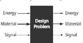
An engineering system can therefore be initially modeled as a black-box (Figure 2) with energy, material and signal inputs and outputs from the system. In black box modeling, energy is represented by a thin line, material flows by a thick line, and signals by dotted lines as shown. The engineering system therefore provides the functional relationship between the inputs and the outputs.
Problem clarification involves forming a clear understanding of the problem. The overall problem represented by the black-box can be decomposed into smaller sub-problems. Problem decomposition allows solutions to complex engineering design problems to be found by considering simpler sub-problems. Design teams can then focus on the sub-problems critical to the success of the project first, deferring others. Subproblems are then mapped to sub-functions for which a design is created. Combination of all the designs that achieve each of the sub-functions results in the desired system solution that achieves the overall desired function. Note that the functional decompositions and the resulting black-box diagrams are generic and do not commit the design team to any particular technological working principle.
Black-box modeling of existing systems that are to be redesigned, on the other hand, decomposes the existing system into sub-systems as opposed to sub-functions. The sub-systems would then be translated to subfunctions from where the redesign proceeds.
4.1 Black-Box Modeling Examples
Throughout the paper two examples found in the TRIZ literature will be used. They are presented here to illustrate the use of black-box models.
4.1.1 Automobile Airbag
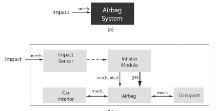
The automobile airbag, when used in conjunction with a seat belt, provides protection to occupants during front end collisions. Airbag systems deploy when crash sensors located on the front of the vehicle detect high-rate deceleration. The sensors trigger the inflator module that through a rapid chemical reaction (a miniexplosion) rapidly releases nitrigen gas that fills the airbag. Typically the air-bag will be fully deployed within 1/20 th of a second after impact detection (Kowalick, 1997). An initial black-box model of the airbag system is presented in Figure 3(a). The entire airbag system is represented as a black-box with a single input, the mechanical energy from the automobile impact. Figure 3(b) illustrates the decomposition of the black-box into sub-systems, with the corresponding the energy, material and signal flows.
The sequence of events, indicated by the arrows, starts with the detection of an impact, that signals the chemical reaction, rapidly releasing gas and mechanical energy into the airbag. The occupant then slams into the airbag, that in turn collides with the car interior. Note that the double arrows between the occupant and the airbag, and the airbag and the car interior are used to indicate that the mechanical forces are bi-directional.
4.1.2 Computer Hard Drive
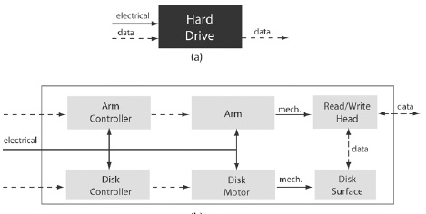
A computer hard drive is used to store and retrieve data (Figure 4). Within the hard drive, data is stored on a rotating magnetic disk, from which data is read using a read/write head. The head, situated at the end of a moveable actuator arm, can magnetize (write) or sense the magnetic field (read) on the disk. The head floats on the airflow generated by the disk rotation that maintains a very small gap between the two, preventing contact that may result in data loss. A black-box model of the hard drive in operation is shown in Figure 5.
5. Energy-Material-Signal (EMS) Models in TRIZ
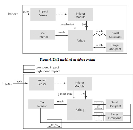
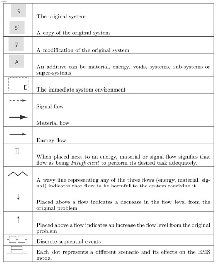
The EMS model extends the black-box model by incorporating symbols that indicate harmful and insufficient energy, material and signal flows with in the system. In addition, symbols are also included to allow the modeling of multiple scenarios and discrete time-separated events. Table 1 lists the new symbols with their corresponding description. The EMS model will be explained in the context of the previous two examples. Despite the success of airbags at saving lives, they have also resulted in numerous deaths to smaller occupants due to their deployment force. An EMS model of the airbag system during a frontal impact is illustrated in Figure 6. A comparison of the black-box model and the EMS model shows that the main difference between the two is that in the EMS model, the generic occupant is now separated into a large and a small occupant, with the harmful effect of the mechanical energy on the small occupant shown. Within the context of the airbag system, one can clearly identify where the problem is that requires further attention. In addition, available system resources that could be used as part of the design solution are integrated into the problem clarification model. As such a separate list of resources is not required, as is traditionally the case if SFA or TOP analysis methods are used.
Table 1. EMS model symbols and description. System could mean an assembly, sub-assembly, function, user, and so on
To reduce airbag caused fatalities, numerous automakers have installed de-powered airbags. The bags do not deploy as fast as the original ones and therefore do not cause harm to small occupants. The problem with de-powered air bags, however, is that they are less effective during high-speed crashes. This is because the time it takes to achieve full deployment for the de-powered airbag is not fast enough to prevent the occupants (both large and small) from hitting the interior of the vehicle. The two scenarios, low-speed and high-speed collisions, are illustrated in the EMS model in Figure 7. Using the multiple scenario symbol, the low speed impact scenario is represented by the top slots. In this scenario, the mechanical force from the airbag is sufficient to shield both types of occupants from colliding with the vehicle interior. In the second scenario, high-speed impact represented by the lower slots of the multiple scenario symbols, also results in airbag deployment. However, the mechanical force from the airbag is insufficient to prevent either occupant from colliding with the vehicle interior (harmful effect).
Turning to the hard drive example, an area of concern arises when the computer is off and receives a hard external knock. Without the hard drive disk spinning, the head can be knocked off its rest position and data on the disk destroyed. In the rest position, the head is typically held in place by a magnetic latch. When the computer is powered on again, the airflow from the disk motion raises the head, and a permanent magnet/electro-magnet system situated at the arm axes of rotation (the pin) generates enough force to release the arm from the magnetic latch and move the head to wherever data needs to be written or read (Royzen, 1999). An EMS model of this scenario is illustrated in Figure 8. In the model, one can track the sequence of events (the flow) from when the computer chassis receives a hard knock to the point where there is damage (harmful effect) to the disk surface by the read/write head. In the figure, the magnetic field is shown to be insufficient, and therefore an area that would be addressed.
A possible solution may be to use a stronger magnetic latch. This, however, may present its own problem by making it difficult for the arm to be released during start-up. The two scenarios are modeled in Figure 9, where the top slot in the multiple scenario symbols represents the hard knock scenario, and the lower slot the computer start-up. Note that by increasing the magnetic strength of the latch, a desirable effect is achieved in response to reduction of damage from external knocks, but it also produces an undesirable effect during system start up.
The two examples presented have served to illustrate how EMS models can be developed to identify where harmful or insufficient effects occur in a system, focusing engineering designer’s attention to those areas. In addition, the models present the problem area in the context of the overall system allowing engineers to see what resources are available that may be used as part of a solution. Further, unlike traditional black-box modeling, the EMS models allow the inclusion of multiple scenarios within the same model.
6. EMS Models and the 76 Standard Solutions
The 76 standard solutions are to a large extent, based on the substance-field modeling method. To effectively use the EMS models, therefore the solutions were modified and articulated in terms of EMS models. In addition, several authors have noted the significant degree of repetition amongst the standard solutions, developing their own reduced versions. Soderlin (2002) preferring to use `rules’ as opposed to ‘standards’, reduced the number of solutions from 76 to 16 rules. Orloff (2003) renames the standard solutions as ‘compact standards’, and reduces the number to 35.
In this work, suggestions put forth by Soderlin (2002) and Orloff (2003) have been taken into account while generating a set of Condensed Standards composed of 27 solutions. In addition to reducing the number of solutions from 76, the Condensed Standards, (a) use the language and jargon typical in engineering design, and (b) replace the substance-field models found in the original 76 solutions with the EMS models. The classical 76 standard solutions fall into five classes:
1. Class I: Improving the system with little or no change
2. Class II: Improving the system by changing the solution
3. Class III: System transitions
4. Class IV: Detection and measurement
5. Class V: Strategies for simplification.
The Condensed Standards have reduced these five classes to three sets of standards:
1. Condensed Standards I: Improving the system with little or no change
2. Condensed Standards II: Improving the system by changing the solution
3. Condensed Standards III: Detection and measurement
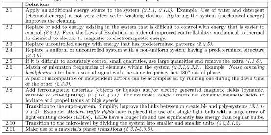
The Condensed Standards incorporating the EMS models are presented in Tables 2 – 4 in the Appendix. Within the tables, the numbers in italics refer to the classic TRIZ standard solutions on which the condensed set are based. Where applicable, solution fragments based on the EMS model are included.
7. Concluding Remarks
TRIZ has been widely recognized as a powerful systematic concept generation technique that is applicable to a wide array of disciplines. This paper has described the development of a new modeling method, energymaterial- signals (EMS) models based on the black-box models found in engineering design. By adapting a method already familiar to engineering designers it is hoped that one of the barriers to wider TRIZ implementation within the engineering design community will be removed.
References
Kowalick, J., (1997) “ ‘No-compromise’ Design Solutions to the Air-Bag Fatalities Problemâ€, Triz Journal, no. 7..
Orloff, M., (2003) Inventive Thinking through TRIZ: A Practical Guide, Springer, Berlin.
Pahl, G. and Beitz, (1996) Engineering Design. A Systematic Approach, 2nd Edition, Springer-Verlag, London.
Royzen, Z., (1999), “Tool, Object, Product (TOP) Function Analysis’â€, TRIZ Journal, no. 9.
Soderlin, P., (2002), “TRIZ The simple wayâ€, TRIZ Journal, no. 2.
Appendix: Condensed Standards
Table 2. Condensed Standards I (9 solutions): Improving the System with Little or no Change. This class looks at ways to modify a system in order to produce a desired outcome or eliminate an undesired one. An additive can be material, energy, voids, systems, sub-systems or super-systems.

