Creative Design Of Wafer Transport Mechanism
Editor | On 02, Jul 2004
By: Long-Chang Hsieh and Hsin-Sheng Lee
Long-Chang Hsieh and Hsin-Sheng Lee, jennifer@sunws.nhust.edu.tw
Department of Power Mechanical Engineering,
National Huwei University of Science and Technology
Yunlin, TAIWAN
Abstract
At present, the vacuum robot commonly used by semiconductor factories can be roughly divided into two types: one is the SCARA-type robot; the other is the frog-leg type robot. No matter which type of robot is adopted, its number of power sources is more than 3. In order to reduce the number of power sources of the robot and realize the goal of reducing the equipment expenditure, in this paper we will focus on the cluster wafer transport mechanism, make use of the creative design method, TRIZ. Using the creative design software, TechOptimizer, we will evaluate it, have designed 9 mechanism design schemes that can not only save cost, and also act according to the required motion of the three subsystems, i.e. ascending, rotating and holding. From these mechanism design schemes, 3 were chosen for the purpose of discussing the motion rules and simulating the motion trace. The achievements of this paper not only can serve as a reference to the industrial circles for developing a wafer transport mechanism, but also can serve as a teaching tool for creative mechanism design courses.
I. Preface
Due to the vigorous development of semiconductor products in all countries in the world and the attention paid to the high-tech products at home, all the manufacturers in Taiwan are urged to participate in the research work of the semiconductor manufacturing process and equipment. However, the semiconductor industry is different from general traditional industries and demands a very high standard both in manufacturing process and equipment, high productivity, high efficiency, high quality products, and high reliability have become the indispensable basic requirements for the semiconductor manufacturing process. In order to raise the productivity of wafer manufacturing, the size of wafers produced by the semiconductor manufacturing factories will develop from the present 200 mm towards the goal of 300 mm.
At the forefront of the semiconductor manufacturing process, the wafer manufacturing must pass through a succession of manufacturing steps, including such processes as optical development, rapid high-temperature manufacturing process, chemical vapor deposition, ion planting, etching, chemical/mechanical grinding and manufacturing process monitoring, etc. Therefore, due to the factors of reducing the wafer surface pollution, lowering the equipment cost, shortening the production cycle, and increasing the output, the application of the integrated manufacturing process, cluster tool equipment has become the main development tendency of equipment at the forefront of the semiconductor manufacturing process. In the cluster tool equipment, the robot is in charge of the transport motion of the wafer in every module.
In the past years, the research and design of wafer transport mechanisms has been the subject of some studies [1-7] . Most of them focused on research of the motion control of the end-effector of wafer transport mechanisms. And, some of them focused on the design and manufacture of wafer transport mechanisms. No one focused on the subject of creating new design concepts for wafer transport mechanisms. The purpose of this paper is to present a systematic approach for the creative design of wafer transport mechanisms.
In order to reduce the number of power sources of the robot and realize the purpose of reducing the equipment expenditure, this paper will focus on the cluster wafer transport mechanism, make use of the creative design method, TRIZ [8] , and via the creative design software, TechOptimizer, evaluate it, and design 9 mechanism design schemes that can not only save cost, but also act according to the required motion of the three subsystems, i.e. ascending, rotating and holding. From these mechanism design schemes, 3 were chosen for the purpose of discussing the motion rules and simulating the motion trace. The achievements of this paper not only can serve as a reference for industrial circles for developing wafer transport mechanisms, but can also serve as a teaching tool for creative mechanism design courses.
II. Kinematic analysis of cluster tool equipment
In today’s 8-inch wafer factory and 12-inch wafer factory, the cluster tool equipment [1] has become a necessity. The cassette, robot, cluster tool, and process modules construct the cluster tool equipment, as illustrated in figure 1. Because the cluster tool equipment acts in a vacuum environment instead of holding the wafer by means of adsorption, supporting it on a platform tray at the end of the robot arm, making the wafer attached to the supporting utensil by means of friction. In supporting the wafer, the robot must keep stable, preventing the wafer from flying out due to large acceleration. In the meanwhile the robot can shorten the transport journey, lower the overall manufacturing time, and reduce the chance of the wafer being polluted. Therefore, the cluster tool equipment chooses the robot to hold the wafer.
2.1 Cluster tool robot kinematic analysis
In the cluster tool equipment, the motion provided by the robot is mainly horizontal, assisted by the perpendicular motion, as shown in figure 2. The first motion of cluster tool equipment is to rotate a certain angle, β degree. The second motion is to make the rectilinear motion along the radial, so as to make the end-effector advance and countermarch. The last motion is moving up and down the Z-axis to make end-effector taking out or placing the wafer. In order to bring the horizontal motion to the prefixed position, generally there are two modes of designing the mechanism: one is to complete the rotating and the radial motion at the same time; the other is to rotate before making the radial rectilinear motion. As Z-axis is concerned, an independent power source is provided to drive its motion, so as to be in concert with the wafer’s storing positions of different heights.
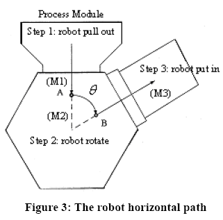
At present the cluster tool robot, whose horizontal path is illustrated in figure 3, mainly adopts the two independent inputs. That means one input makes the circular motion to drive the end-effector to make rotating motion while the other input makes the rectilinear motion so as to render the end-effector capable of sending in or drawing out the wafer. As can be seen at points A and B in figure 3, we know that there are two discontinued points in the robot path layout. Since it adopts the two independent inputs, the advancing and countermarching motion of the end-effector are actuated by the connecting rods group that are driven by the No. 3 motor. And the rotating motion of the end-effector is specially actuated by the No. 2 motor directly and independently. So when the end-effector moves to point A, the No. 3 motor has to stop and the end-effector is then actuated by the No. 2 motor. Furthermore, when the end-effector arrives at point B by rotating θ angle, No. 2 motor has to stop and the arm is then actuated by the No. 3 motor, completing the last stage of rectilinear motion.
Based on the above, we give the following conditional expression: (1) the rectilinear motion is a motion of mutative acceleration (or equivalent acceleration, or equivalent deceleration). (2) The velocities at points A and B are both zero. (3) The circular motion is a motion of equal angle acceleration or equal angle deceleration.
denoting the rotating angle of the end-effector, 0 t is the starting time of the circular section (in this paper it is given as zero), f t is the ending time of the circular section. According to the limited condition, the layout of S(t) for rectilinear motion can be formulated as:
The equation (5) is a non-linear differential equation, whose solution must be worked out by means of the iteration scheme.
2.2 Motion analysis of SCARA robot
The SCARA robot, illustrated in figure 4, is in the configuration of horizontal motion and has three revolute joints. The rotating angle between each rotating axis must maintain a certain ratio in order to cause the robot to drive its end-effector to
make rectilinear motion. Suppose the arm lengths of the axis rods are respectively 1 l , 2 l , 3 l , the rotating angle of the first rotating axis is 1
θ , the rotating angle of the second rotating angle is 2
θ , the rotating angle of the third rotating axis is 3
θ , the limited condition is that the third rod must be constantly in the same carriage so as to complete the rectilinear motion. According to the figure, the positions of points C and
D can be expressed as:
III. Subsystems of wafer transport mechanism
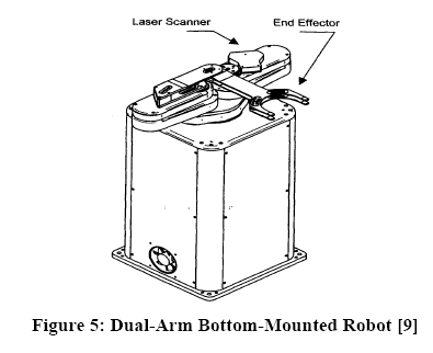
The Dual-Arm Bottom-Mounted Robot, DBM, is one of the present cluster wafer robot mechanisms, the mechanism driven by four-power source. Its external shape is shown in figure 5 [9] . The whole system can perform the motions of three subsystems as follows:
(1) The subsystem that rotates 90° to-and-fro around the Z-axis.
(2) The subsystem that moves up and down Z-axis.
(3) The subsystem that makes the back-and-forth rectilinear motion with the end-effector on the mechanism platform that can hold and support the wafer.
The goal of this paper is to construct a new system by ameliorating and conforming these three subsystems. It lists all three practicable subsystem schemes and mutual collocation of the subsystems will produce even more new mechanisms.
3.1 The subsystems that turns 90° to-and-fro around Z-axis
(1) Cam mechanism: the mechanism that makes the platform rotate 90°to and fro, by making use of the grooved barrel cam collocated by the platform bottom dowels, as illustrated in figure 6(a).
(2) Belt transmission mechanism: the mechanism where the motor transmits the power to Z-axis via the belt and belt pulley, causing the whole platform to rotate, as illustrated in figure 6(b).
(3) Gear mechanism: the mechanism where the motor transmits the power to Z-axis via the gear pair, causing the whole platform to rotate, as illustrated in figure 6(c).
3.2 The subsystem that moves up and down Z-axis
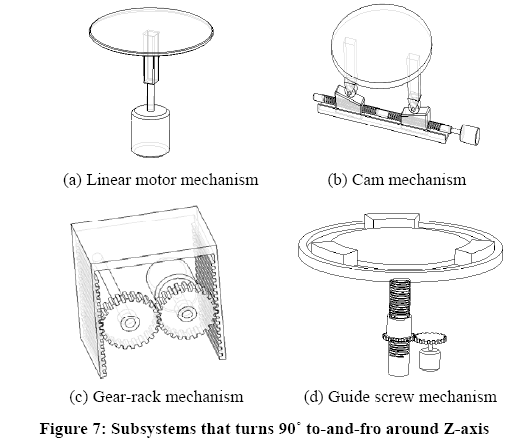
(1) Linear motor mechanism: the linear motor is fixed below the platform, directly drives the platform to rotate, and makes the whole platform move up and down Z-axis, as illustrated in figure 7(a).
(2) Cam mechanism: the mechanism that connects the motor, then the cam slider, and then the above platform by making use of a guide screw whose threads on two sides are opposite. It utilizes the positive reversal of the motor to control the slider from approaching or going far away, so as to make the platform move up and down Z-axis, as illustrated in figure 7(b).
(3) Gear-rack mechanism: it makes use of the gear-rack to drive the platform up and down Z-axis, with one gear connected with the motor as the driver, and the gears connected nearby as driven. It can utilize the positive reversal to control the platform’s moving up and down, as illustrated in figure 7(c).
(4) Guide screw mechanism: the mechanism that has the guide screw fixed below the platform, collocated by a roller, on which a gear is attached and connected to the gear of the motor power source. When the gear of the motor power source begins to turn, the roller is turned to further drive the guide screw to move up and down Z-axis, as illustrated in figure 7(d).
3.3 The subsystem that makes the back-and-forth rectilinear motion with the arm that can hold and support the wafer
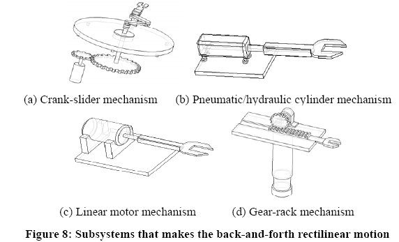
(1) Crank-slider mechanism: the mechanism where the platform is equipped with a crank- slider, further makes use of gear that is connected with the connecting rod, collocated by a power source gear, and can render the end-effector to make the back-and-forth rectilinear motion as soon as the motor turns once, as illustrated in figure 8(a).
(2) Pneumatic/hydraulic cylinder mechanism: an arm is fixed at the front end of the pneumatic/hydraulic cylinder. As long as the pneumatic/hydraulic cylinder is actuated, the end-effector will make the back-and-forth rectilinear motion, as illustrated in figure 8(b).
(3) Linear motor mechanism: the arm is fixed at the front of the linear motor. As long as the linear motor is actuated, the end-effector will be driven to make the back-and-forth rectilinear motion, as illustrated in figure 8(c).
(4) Gear-rack mechanism: a platform with sliding orbit is fixed on the platform, the end-effector is at the end of the rack, and driven by the power source gear to make the back-and-forth rectilinear motion, as illustrated in figure 8(d).
IV. Creative design of wafer transport mechanism
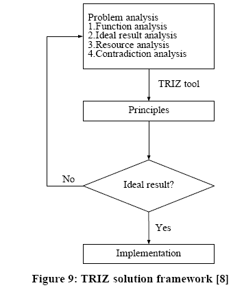
The goal of this paper is to construct a new system by ameliorating and conforming the above mentioned three subsystems. The research findings reveal that, neither the amelioration of reducing one power source, nor that of replacing the original three or four power sources with a new mechanism, can conform the collocation of the subsystem that moves up and down the Z-axis and the other two subsystems. The reason lies in the fact the system of making the motion along the Z-axis to support the cassette of different heights is one that needs a completely independent motion. It cannot conform to the other two subsystems. Therefore, by making use of the TRIZ creative method [8] , we conform and ameliorate the subsystem that rotates 90°to and fro around the Z-axis and holds and supports the robot to make the back-and-forth rectilinear motion, and devise a new system that only needs two power sources. Its solution framework is illustrated in figure 9.
4.1 Dual-system integrated mechanism analysis
(1) Function analysis: we need a platform that can rotate 90° to and fro around the Z-axis and move up and down the Z-axis. In the meanwhile, we need an end-effector that can support the wafer and make the back-and-forth rectilinear motion.
(2) Ideal result analysis: the mechanism (DBM) now available is the independent motor input source system, driven by four motors. If it has three independent motion systems, it needs at least three motors so as to rotate 90° to and fro around Z-axis, make the up-and-down along Z-axis, and make end-effector back-and-forth rectilinear motion. So if one motor can be reduced, the control system and cost are improved.
(3) Resource analysis: we must attain a platform that rotates 90° to and fro around the Z-axis and move up and down along Z-axis. In the meanwhile, we need an end-effector that can hold and support the wafer and make the back-and-forth rectilinear motion. There are three motors available.
(4) Determining the contradictory area: physical contradictions will arise when one motor needs to drive two independent motions. [Scheme 1-2] Dual-cam mechanism
(1) Solution concept:
In order to render one mechanism to make two actions, this scheme adopts the cam [10] , connecting two cams in series. As long as cam trace curve can be designed, one power source will be enough to execute two actions, with two cams respectively controlling the end-effector’s back-and-forth motion and the rotation of the platform. This scheme uses the time separation theory based on the TRIZ physical contradiction separation method to seek the solution and TechOptimizer [11] to find out the solving approach, as illustrated in figure 10.
(2) Amelioration result 1:
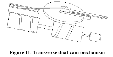
Put one end of the cams in series below the platform, make use of the first cam to connect the connecting rod, and fix end-effector to the platform. When the first cam rotates, the connecting rods connected by a dowel will advance along the cam groove, causing the end-effector to move back and forth. Then make use of the dowel that is driven to move at the bottom of the platform when the second cam rotates, so as to allow the platform to rotate 90° to and fro around Z-axis. Therefore, in designing the cam groove, we should merely see to it that when the first cam rotates, a collocated work will also rotate and when the second cam groove is a straight one, another immovable work will remain motionless, so as to meet the standard time separation. The subsystem that moves up and down Z-axis can be referred to the subsystems in Section 3-2, anyone of which can be chosen for the collocation. The transverse dual-cam mechanism is shown in figure 11.
(3) Amelioration result 2:
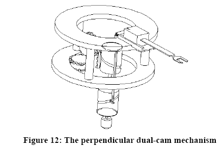
This scheme makes use of the combination of two cam in series, collocated by the under cam to connect the connecting rod to the end-effector of the above platform. It also makes use of the cam rotation to drive the connecting rod to move up and down and further render the end-effector to move back and forth. In the meanwhile, the above cam will be collocated by a rack, that is, the compound gear that has bevel teeth and spur teeth at the same time. When the rack is driven to move up and down, the gear will move together with the internal gear of the platform, causing the platform to rotate. The subsystem that moves up and down Z-axis can be referred to the subsystems in Section 3-2, anyone of which can be chosen for the collocation. The perpendicular dual-cam mechanism is illustrated in figure 12.
[Scheme 3-4] One-way clutch mechanism
(1) Solution concept:
First imagine a driving force source has to complete the rotation around the Z-axis and drive the end-effector to move back and forth. When an action is progressing, another action must be stopped. Since the servomotor can be positively reversed, numerous new systems combining two reverse one-way clutches and one servomotor can meet the requirement. This scheme seeks the solution by using the time separation theory of the TRIZ physical contradiction separation approach.
(2) Amelioration result:
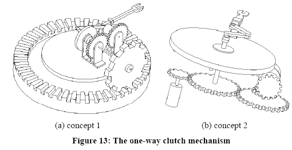
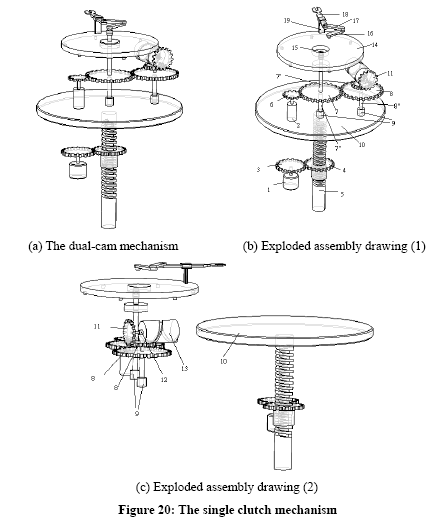
First let the platform combined with a concentric coronary gear. The platform is connected with the bearing, rod and crown gear, a crank-slider mechanism is set up on the platform, and then we fix a transmission shaft, collocated by the gear connected with the power source motor nearby. A crank- slider is fixed to one end of the transmission shaft, the latter connected with the former via a one-way clutch. But the other end of the transmission shaft is collocated by another gear, in the meanwhile connected with the crown gear of the outer circle. However, there is a second one-way clutch between the transmission shaft and the gear while the two one-way clutches in the mechanism are opposite in direction. When the motor turns clockwise, the crank-slider is actuated so as to make the arm complete the back-and-forth motion. Though the other end of the transmission shaft is still rotating, the power will not be transmitted to the gear, for the second one-way clutch is in the state of separation. On the contrary, when we make the motor rotate anti-clockwise, the rotation of the transmission shaft will only have influence on the gear connected with the crown gear. But the end-effector is immobile. Then the gear will take the platform as its central point, driving it to rotate around the fixed crown gear and complete the rotating action of the Z-axis. The subsystem that makes the up-and-down motion along Z-axis can be referred to the subsystems in Section 3-2, anyone of which can be chosen for the collocation. The one-way clutch mechanism is illustrated in figure 13(a).
(3) Amelioration result 2:
First design a crank-slider on the platform as the mechanism to support the wafer, then connect the crank-slider with the connecting rod of the driving source by a one-way clutch, and fix to it a bearing through the platform. Below it there is a pair of gears that move together with the motor, causing the other end of the connective gear to be connected with a pair of compound gears. The bevel gear on the compound gear is connected with a one-way clutch and a cam, thus completing the whole mechanism. The working theory requires that the two one-way clutches are driving in opposite directions. When motor turns in one direction, it first drives the crank-slider on the end-effector to move back and forth. Then the relationship of simultaneous motion that exists between the gears may also drive the compound gear, we are able to prevent the running from passing to the cam by using the one-way clutch, which also maintains the fixation of the platform. While the motor turns conversely in another direction, the crank-slider will not be influenced thanks to the one-way clutch. Then the cam that is driven is the one on the compound gear. The rotation of the cam will affect the dowels below the platform, causing the platform to rotate 90° to and fro around Z-axis. The subsystem that makes the up-and-down motion along Z-axis can be referred to the subsystems in Section 3-2, anyone of which can be chosen for the collocation. The other one-way clutch amelioration mechanism is shown in figure 13(b).
[Scheme 5] Endface cam mechanism
(1) Solution concept:
Since our goal is to conform the two functions of the platform that rotates 90° to and fro around Z-axis and makes the back-and-forth rectilinear motion along the end-effector. These two functions will be made to be fulfilled by one system, the conception of which follows the theory of “transferring many functions to one work element†in the TRIZ idealization principle. The traditional mechanisms where the platform either rotates 90° to and fro around Z-axis or makes the rectilinear motion along the arm are both moving on the platform. But this scheme hopes to make the end-effector unwind at the end that is 90° away from the platform, so as to support the wafer and rotate another 90° to the other end to place the wafer, repeating this action to and fro without necessarily turning the whole platform along with it. So first we segment the system, allowing the actions of support for the wafer and rotating become independent of each other, giving the action of rotation to an independent motor, and making use of the rotation to combine the platform with the robot, accomplish the action of supporting the wafer. Hence the conception of the endface cam mechanism happened.
(2) Amelioration result:
First design a platform, on which a mountain-like cam is built between the two ends that are 90° away from each other, in the middle a power source motor is fixed, above which is connected a connecting rod whose front part is a four-bar linkage. The connecting rod at the extreme edge is the end-effector, supported by an arm rack. The two connecting rods in the middle are connected by a dowel with the roller, under which opposite is the mountain-like cam. The working theory is that when the motor turns, all the linkages will circle around the motor’s axis rod in one direction, at the same time driving the roller to gradually climb onto the mountain-like cam and causing the end-effector to unwind step by step, so that it will fully extend as soon as it reaches the place just opposite the cassette. Then the roller also reaches the highest point of the mountain-like cam. Then the whole system accomplishes the supporting action, collocated by a subsystem that allows the platform to move up and down the Z-axis. When the motor turns back, the roller will climb down the mountain-like cam, causing the end-effector to draw back. When it approaches the other end, the roller will climb again onto the mountain-like cam, causing the end-effector to unwind again. It works in this way to and fro, accomplishing the process of the platform’s rotating 90° to and fro around the Z-axis and making the back-and-forth rectilinear motion along the end-effector. The subsystem that moves up and down the Z-axis can be referred to the subsystems in Section3-2, anyone of which can be chosen for the collocation. The platform cam mechanism is illustrated in figure 14.
4.2 Four-axis (Dual-arm) power source mechanism analysis
(1) Function analysis: we need a platform that rotates 90° to and fro around Z-axis and moves up and down Z-axis. In the meantime, we need an arm on the platform to hold and support the wafer and make the back-and-forth rectilinear motion.
(2) Ideal result analysis: since all the mechanisms available are four-axis independent motor input source systems, in designing the new mechanism scheme we should take it as the premise to maintain the final function without changing the number of driving force source equipment.
(3) Resource analysis: we need an end-effector that rotates 90° to and fro around Z-axis and moves up and down Z-axis. In the meanwhile we need an end-effector on the platform to hold and support the wafer and make the back-and-forth rectilinear motion. There are four motors available.
(4) Determining the contradictory area: we ameliorate the end-effector with the goal of attaining the same function without changing the number of motors.
[Scheme 1] Four-axis drive vertical robots
(1) Solution concept:
The traditional DBM mainly adopts the plane-type design, but this scheme improves the four-axis robot by using the “Moving to a new dimension†principle in the TRIZ method. It turns the original action of driving the end-effector to advance, countermarch, and rotate by taking the Z-axis as the rotating center into one that takes the vertical plane as the rotating center, so as to put into practice the idea of moving the end-effector up and down, advance and countermarch.
(2) Amelioration result:
We change the original plane design of the robot into the vertical design. Below the end-effector base, there is a motor helping the belt to control the rotation of the whole robot, the rest three motors respectively adjusting their operations to accomplish the actions of the end-effector advancing, countermarching, ascending and descending. The four-axis drive vertical robot is illustrated in figure15.
4.3 Three-axis power source mechanism
(1) Function analysis: we need a platform that rotates 90° to and fro around Z-axis and moves up and down Z-axis. In the meanwhile we need an end-effector on the platform to hold and support the wafer and make the back-and-forth rectilinear motion.
(2) Ideal result analysis: since all the mechanisms now available are four-axis independent motor input source systems that need four motors to drive. If they are three independent motion systems, they need at least three motors. We hope to use three motors as a power source to design a new mechanism scheme.
(3) Resource analysis: we must complete a platform that rotates 90° to and fro around Z-axis and moves up and down Z-axis. In the meantime, we need an end-effector on the platform to hold and support the wafer and make the back-and-forth rectilinear motion. There are three motors available.
(4) Determining the contradictory area: though the number of driving motors is reduced, the same action requirement can still be met.
[Scheme 1] Three-axis movable robot
(1) Solution concept:
In order to reduce the four motors to three motors, we use the “space separation†method in the TRIZ separation principle to seek the solution. First analyze every action of the arm, put some subassemblies in these action positions to connect every action position. On the original reference model, the plane-type DBM Robot, the robot (control arm) turns 90° to and fro around Z-axis, forming three independent power centers together with the advancing and countermarching actions of the arm. Because the actions of the three power centers are quite similar, we amalgamate the similar actuating modes, using two power centers to complete the original actuations.
(2) Amelioration result:
The three-axis movable robot is illustrated in figure 16. Fix the robot on a platform base that can climb and descend with the actuation of the motor. The ascending and descending actions of the whole robot will be accomplished by the bottom motor (M1). The bottom end of the end-effector on the movable platform base is actuated by the second motor (M2), controlling the rotating action of the whole robot. The third motor (M3) is fixed on the uppermost of the end-effector, which drives the gears that further drives the rack in the sliding orbit, finally causing the tray at the end-effector to make the back-and-forth actions.
[Scheme 2] Crank-slider three-axis mechanism
(1) Solution concept:
In the systems we mentioned above, the platform is collocated by subsystems, causing the platform to move along the Z-axis. Because the whole platform is rather heavy, a large amount of power must be used. The purpose of this scheme is to make the end-effector that supports the wafer ascend and descend to a fixed position, so as to perform the supporting or placing action. It is not necessary for the arm to move up and down with the whole platform. Therefore, the traditional mechanism that moves up and down the Z-axis is segmented to the platform by means of the “segmentation†theory in the TRIZ method.
(2) Amelioration result:
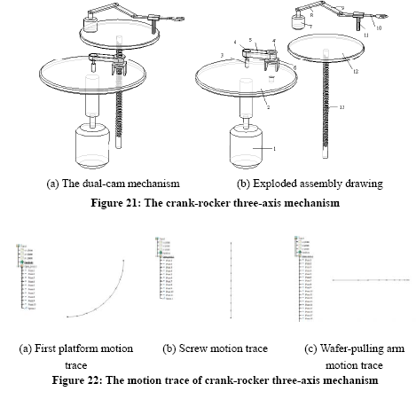
First along the platform center span on-line a small platform with a fixed motor that is connected with the two connecting rods connected with the end-effector, forming a crank-slider mechanism. At the same time there is an immovable bracket on the end-effector, below the platform is a guide screw, collocated by a sleeve with internal screw thread, and outside the sleeve is collocated by a belt that is connected with the second motor on the platform, completing the whole mechanism. When we want to control the end-effector that supports the wafer at varied heights, we merely have to control the motor that collocates the belt, which drives the sleeve with internal screw threads to turn, enabling the guide screw to connect the platform and move up and down replacing the up-and-down motion originally needed along the Z-axis. When the end-effector arrives at a fixed position, it will make the arm move back and forth as long as the motor that actuates the crank-rocker is controlled. The actions of the platform rotating to and fro around the Z-axis can be completed with the collocation of other subsystems. In this scheme a motor is directly connected below the platform. The crank-slider three-axis mechanism is illustrated in figure 17.
[Scheme3] Orbit bodywork mechanism
(1) Solution concept:
In order to design a power source that can make the platform rotate 90° to and fro around the Z-axis, this scheme employs the TRIZ “equipotentiality†theory to seek a solution. As long as the moving route of the end-effector can be changed, it will replace the platform to rotate 90° to and fro around the Z-axis, keeping the whole platform motionless. Then only the end-effector will reach a fixed position.
(2) Amelioration result:
In order to design on the platform an orbit bodywork mechanism, an orbit that reaches the platform whose two ends are 90° away from each other must be fixed on the platform, a structure that carries the robot. The end-effector that supports that wafer on the bodywork is a gear-rack mechanism, connected and fixed on the bodywork by a motor. When we want to support the wafer, the supporting end-effector will, as long as the motor that is connected with the robot is actuated, advance into the cassette, complete the supporting action, and drive the bodywork to advance towards another orbit. Such a cycle will replace the platform to rotate 90° around the Z-axis and the end-effector to make the back-and-forth motion. The platform that acts up and down the Z-axis can be collocated by other subsystems. In this scheme we choose the guide screw. As long as the orbit between the two ends that are 90° away from each other is connected below the flat and further strengthened with a guide screw, the orbit bodywork will be able to act along the Z-axis instead of the platform when it reaches the fixed positions at the two ends. The orbit bodywork mechanism is illustrated in figure 18.
4.4 Discussion
Aimed at the wafer transport mechanism, this paper makes creative design of the dual-system mechanism integration, the four-axis (dual-arm) power source mechanism and the three-axis power source mechanism, ameliorating the DBM mechanism now available and adopt many cam and single clutch designs. The research findings reveal that: (1) the subsystems that move up and down the Z-axis cannot be conformed to combine the other two subsystems. (2) There must be 2 sources for the driving force. (3) In conforming the subsystems that rotates 90°to and fro around Z-axis and makes the back-and-forth rectilinear motion along the end-effector, we cannot avoid using the cam or single clutch design. That the second element and the third element cannot be broken is attributed to the first element. Moreover, in the subsystem analysis, the guide screw that is capable of self-locking effect and high in the degree of precision is the best design to the subsystem that moves up and down the Z-axis. Since the wafer adopts the supporting mode, it is not suitable for the subsystem where the end-effector makes the back-and-forth rectilinear motion to adopt the pneumatic/hydraulic cylinder mechanism whose speed is too high.
V. Amelioration design scheme kinematic analysis
From the nine wafer transport robot creative design schemes, this paper chooses three design schemes, i. e. the dual-cam mechanism, one-way clutch mechanism, and crank-slider three-axis mechanism to illustrate their motion rules and simulates their motion traces.
(1) Dual-cam mechanism
The dual-cam mechanism is illustrated in figure 19(a), the exploded assembly drawing is shown in figure 19(b) and figure 19(c). This mechanism is made up of 17 parts that operate mutually to satisfy the design demand. This mechanism is divided into three parts. The first part is the advancing and countermarching of the wafer-pulling arm. Motor 1 drives cams 2 and 3 to move together, when cam 2 drives the connecting rod 9, the connecting rods 9 and 10 drive the slider 11 to slide along sliding orbit 8’, and further push the wafer pulling end-effector to make the back-and-forth motion. In the second cycle of cam 2, the wafer-pulling end-effector 12 makes the back-and-forth motion. In the second part, motor1 drives cams 2 and 3
to move together, when cam 3 drives rack 4 to make the ascending (descending) motion, with rack 4 driving spur gear 5, for gear 5 (including Nos. 6 and 6’) is a compound gear, another gear is the bevel gear 5’, which drives together with the compound gears 5 and 5’ the compound gears 6 and 6’, and further drive the internal gear 7 in the rotating platform 8 to rotate. The 90°to-and-fro rotating motion of the rotating platform 8 is sliding along the circular orbit 13. In the rotating cycle of cam 3, the rotating platform 8 can be driven to make the 90°to-and-fro motion. In the third part, the ascending and descending motion of the rotating platform 8 is controlled by motor17. When motor17 rotates, the spur gear16 will drive gear 15 to make negative turn, causing the screw 14 to move up and down and pushing the rotating platform 8 to move up and down as well. This design, under the condition of the same motor, respectively produces the action of the wafer pulling arm advancing and countermarching and that of the platform rotating, having met the design request.
(2) One-way clutch mechanism
The one-way clutch mechanism is illustrated in figure 20(a), the exploded assembly drawing is shown in figure 20(b) and figure20(c). This mechanism is made up of 19 parts that operate mutually to satisfy the design demand. The rules for the motion of this mechanism can be divided into three parts. The first is the part of the platform moving up and down. When motor 1 rotates, the spur gear 3 drives gear 4 to turn, causing the screw 5 to move up and down. The second part is dominated by the positive turn of the motor (clockwise, that is). The third part is dominated by the negative turn of the motor. First, No. 2 motor is controlled by the computer to make the turning motion. When the motor makes the positive turn, gear 6 is brought to make the positive turn, and in turn it drives the spur gear 7, which is, by means of No. 7’ column (forming the gyration pair with the rotating platform 14) to be connected with the single clutch15 (this single clutch can only be integrated into the operation when the motor is making the positive turn), and then via the crank 16 and connecting rod 17, renders the wafer pulling arm 18 to make the advancing and countermarching actions. When the motor makes the positive turn, the single clutch 15 breaks away and cam 13 will not turn. So the rotating platform14 also will not turn. The rotating action of platform14 is controlled by cam13. When the motor makes the negative turn, the single clutch 15 breaks away and the arm stops operating. Then the single clutch 12 joins to make the bevel gear 11 and cam13 combine to produce the rotating motion. By means of the transferring operation of the works 6, 7, 8, 8’, 11, 12, 13, 14, the power of motor makes cam 13 rotate. When cam 13 rotates, the rotating platform 14 will advance along the groove to make the rotating motion. Via the cam curve design, the rotating platform will be rendered to make the 90°positive (negative) rotating motion in a cam operating cycle. This design, under the conditions of the same motor, respectively produces the action of the wafer pulling arm advancing and countermarching and that of the platform rotating, having met the design request.
(3) Crank-slider three-axis mechanism
The crank-slider three-axis mechanism is illustrated in figure 21(a), the exploded assembly drawing is shown in figure 21(b). This mechanism is made up of 13 parts that operate mutually to satisfy the design demand. The crank-slider mechanism kinematic analysis employs the computer to control motor1 to make the positive (negative) turn. The first rotating platform 2 also makes the positive(negative) motion, so as to complete the 90°to-and-fro motion of the rotating platform 2. When motor 3 makes the positive turn, the motor power is passed via the belt and belt pulley mechanism (belt 5, belt pulleys 4 and 4’) to the screw 13, which forms the relationship of sliding pair with the rotating platform 2 and the supporting rack 6. Therefore the screw 13 climbs. On the contrary, when motor 3 makes the negative turn, the screw 13 descends. When motor 7 makes the positive turn, the wafer-pulling arm 10 will make the advancing and countermarching motion driven by the crank 8 and the connecting rod 9. By conforming the three motor systems in the above, we can finish the crank-rocker three-axis mechanism, so as to meet the design request. The crank-slider three-axis mechanism motion trace is simulated in figure 22.
VI. Conclusion
At present, the vacuum robot commonly used by semiconductor factories has more than 3 power sources. In order to reduce the number of power sources of the robot and realize the purpose of reducing the equipment expenditure, in this paper we focus on the cluster wafer transport mechanism, make use of the creative design method, TRIZ, and via the creative design software, TechOptimizer, evaluate it. We also present 9 mechanism design schemes that can not only save cost, but also act according to the required motion of the three subsystems, i.e. ascending, rotating and holding. From these mechanism design schemes, 3 were chosen for the purpose of discussing the motion rules and simulating the motion trace. The achievements of this paper not only can serve as a reference to industrial circles for developing wafer transport mechanism, but also can serve as a teaching tool for creative mechanism design courses.
References
1. Gwang-luen Wu, ‘ A Study on the Control of a Robot Arm for a Cluster Tool’, National Taiwan University Department of Mechanical Engineering master dissertation, 2000。
2. Ching-Ming Her, ‘ Minimum-Time Trajectory Control of A Semiconductor Waferhandling Robot ’, National Chiao-Tung University Department of Mechanical Engineering master dissertation, 1993。
3. Yu-Jen Huang, ‘ Mechanism Analysis and Motion Control of Wafer Transfer Robot ’, Chung Yuan Christian University Department of Mechanical Engineering master dissertation, 1998。
4. Tsung-Yang Liu, ‘ Dynamic Analysis, Motion Control and Trajectory Planning of Wafer Transfer Robot ’, Chung Yuan Christian University Department of Mechanical Engineering master dissertation, 2000。
5. Jung-Tsung Cheng, ‘ Design and Implementation of Three-Axes Direct-Drive Robot ’, National Taiwan University Department of Mechanical Engineering master dissertation, 1998。
6. Jiun-Yan Lin, ‘ Design and Implementation of Three-Axis Robot ’, Da Yeh University Department of Mechanical Engineering master dissertation, 2001。
7. Tian-Fu Lu, ‘ Design and Implementation of Four-Axis Robot ’, National Cheng Kung University Department of Mechanical Engineering master dissertation, 1990。
8. John Terninko, Alla Zusman, and Boris Zlotin, Systematic Innovation–An Introduction to TRIZ, St. Lucie Press, 1998.
9. Atmospheric Dual-Arm Robot Manual, PRI Automation, Inc., 1998.
10. Application of cam, China Productivity Center, 1987。
11. Invention Machine Corporation, TechOptimizer 3.0 Training Course, 1999.


