Containment ring problem (Impeller burst) IWB Case study
Editor | On 28, Oct 2000
By: Alla Zusman
azusman@ideationtriz.com
Editor’s note: This paper shows the application of the Ideation Workbench Method to the case that was presented in the September 2000, issue of The TRIZ Journal.
Innovation Situation Questionnaire
1. Brief description of the problem
The engineered system, which is designed to contain the fragments resulting from an impeller burst of a maximum-speed fan, consists of the following: a fan, fan shroud (which controls the direction of the air stream), and an armor-steel containment ring. The problem to be solved is that the ring is too heavy and must be reduced in weight by 50%.
2. Information about the system
2.1 System name
The following systemic levels might be considered:
• Containment ring
• Fan
• Air conditioning system
• Aircraft
• Testing of ring
For the ring, the problem is as follows: the ring must be strong to withstand the impact of the impeller fragments, and the ring should not be heavy. For the fan, the problem is as follows: the impeller can burst, but fragments should not fly away.
For the air-conditioning system, the problem is as follows: the impeller can be broken, but the air should be conditioned.
For the aircraft, the problem is as follows: the impeller can burst, but neither people nor equipment should be harmed.
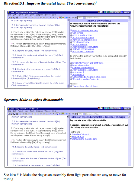
For testing the ring, the problem is as follows: the ring’s ability to capture flying fragments should be tested, but it is difficult to move the heavy ring back and forth. Idea # 1
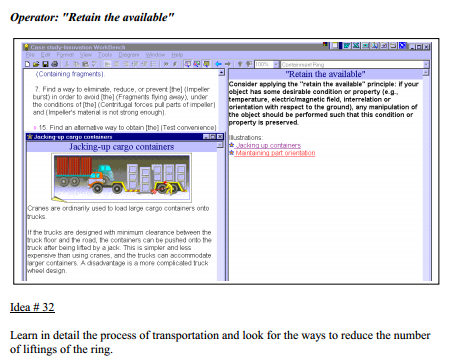
Make the ring as an assembly made of light-weight parts that are easy to move for testing purposes. We can influence two systemic levels: the ring and the fan assembly. Let’s select the fan assembly as the system to be considered.
2.2 System structure
The fan assembly consists of the following elements:
• fan
• motor
• shaft
• motor support
• containment ring
• connectors or support to keep the ring
2.3 Functioning of the system
The primary useful function of the fan is to supply (move) air for the air conditioning system.
The fan rotates quickly and moves air. The air is conditioned so that the aircraft cabin can be supplied with conditioned air.
2.4 System environment
Other parts of the air conditioning system:
• pipes
• heat exchanger
• airflow distributors
Other systems located nearby:
• aircraft covering
• equipment
Other system interacting with the fan and air conditioning system:
• electrical power supply
• air supply
• exhaust air removal
• vibration dampers
Conditions around the system: indoor conditions
3. Information about the problem situation
3.1 Problem that should be resolved
Reduce the weight of the ring by 50%.
The primary harmful function of the given system (the fan assembly) is that impeller fragments fly away if the impeller bursts.
3.2 Mechanism causing the problem
The containment ring must be strong to contain the flying fragments – for this reason the ring is thick and, as a result, heavy.
The cause of an impeller burst is as follows: Rotation of the fan results in centrifugal forces that “pull” the parts of the impeller. The strength of the impeller material can be compromised by material defects and fatigue. As a result, the impeller can burst, causing the impeller fragments to fly off. Due to the high speed at which the fan rotates, the flying fragments carry high energy and can harm people and other parts of
the aircraft.
2.3 Undesired consequences of unresolved problem
The high weight of the ring makes it difficult to carry out the routine tests required by the FAA.
The “dead weight” of the aircraft equipment is also high.
If the weight problem is resolved at the expense of the ring’s strength, the result will be inadequate protection from the flying impeller fragments, which in turn can result in death and/or damage.
2.4 History of the problem
The increased requirements for conditioning the air are met using a higher velocity airflow, but this means that the rotational speed of the fan increases. As a result, an impeller burst becomes more probable and the danger from the flying fragments increases. Because the energy of the flying fragments is increased, the ring must be stronger. As a result, the ring is heavier.
Known attempts to reduce the ring thickness resulted in a reduction in strength.
Idea # 2
Provide high airflow with low rotational speed of the fan. Perhaps utilize several slow fans instead of one that rotates quickly
2.5 Other systems in which a similar problem exists
Similar problems exist in many other areas where weight and mechanical strength are critical issues, as well as other systems for protection against flying parts. We do not have any information about how these problems have been addressed.
2.6 Other problems to be solved
Use an alternative method to contain the fragments. Make the impeller unbreakable.
Others (see the problems on different systemic levels in the beginning of the ISQ).
3. Ideal vision of solution
No containment ring is necessary.
An impeller burst is no longer possible.
4. Available resources
Substance resources
• Material of containment ring
• Material of fan impeller
• Other objects around
• Airflow
Field resources
• Mechanical forces
• Airflow energy
• Electrical energy
• Magnetic field (motor)
Space resources
• Space inside the ring
• Space outside the ring
Time resources
• Time during which the fan is not operating
• Time when the fan is operating
• Time before the impeller bursts
• Time after the impeller bursts
Informational resources: No special resources
Functional resources
• Rotation
5. Allowable changes to the system
• Drastic changes are allowed.
• Any reduction in strength is unacceptable.
6. Criteria for selecting solution concepts
• Weight reduction of at least 30%
• Cost increase of no more than 5%
• About two weeks for new design
• One year for implementation
7. Description of the company business environment
(Withheld)
8. Project data
(Withheld)
Problem Formulation
The Diagram

Prioritize Directions and Generate Preliminary Ideas
The following preliminary ideas have been resulted from the direct analysis of the basic Directions:
3. Utilize a “weak” ring that will absorb energy as it is destroyed
4. Perform testing without removing the ring
5. Reduce the mass of the fragments to reduce damage
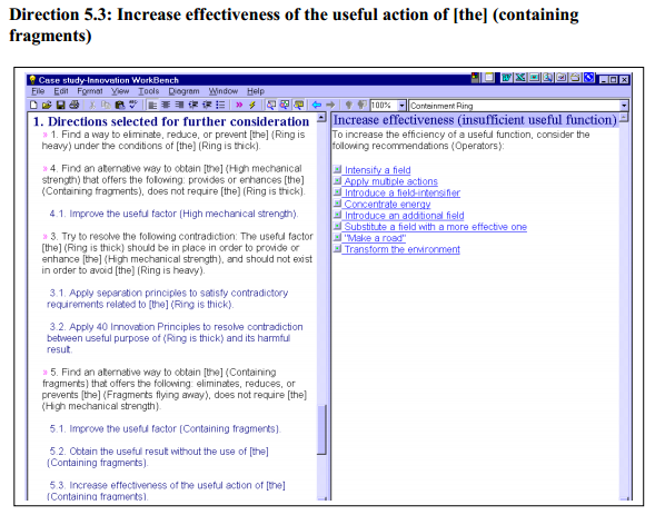
Directions selected for further considerations
Idea # 7
Generate mechanical stress. For example, use additional rings which have been pressure-fitted to create a force directed toward the inside the ring.
Idea # 26
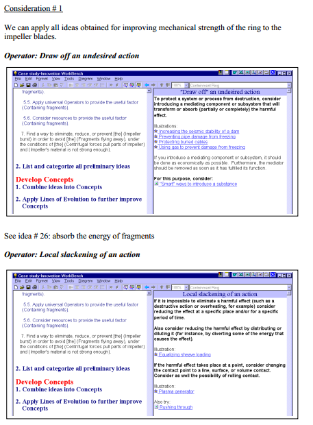
Use foam or foam-like material to absorb energy. Apparently, we need special type of foam like metal foam. We can also consider other fillings that can absorb energy (a see also idea # 3).
List and categorize all preliminary ideas
Idea # 1: Make the ring as an assembly made of light-weight parts that are easy to move for testing purposes.
Idea # 2: Provide high airflow with low rotational speed of the fan. Perhaps utilize several slow fans instead of one that rotates quickly.
Idea # 3: Utilize a “weak” ring that will absorb energy as it is destroyed.
Idea # 4: Perform testing without removing the ring.
Idea # 5: Reduce the mass of the fragments to reduce damage.
Idea # 6: Vary the thickness of the ring tube, reducing the thickness where permissible.
Idea # 7: Introduce preliminary stress. For example, use additional rings which have been pressure-fitted to create a force directed toward the inside of the ring.
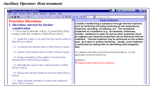
Idea # 8: Use thermal treatment to harden the ring material.
Idea # 9: Use special reinforcing threads (fibers) such as those found in bullet-proof vests.
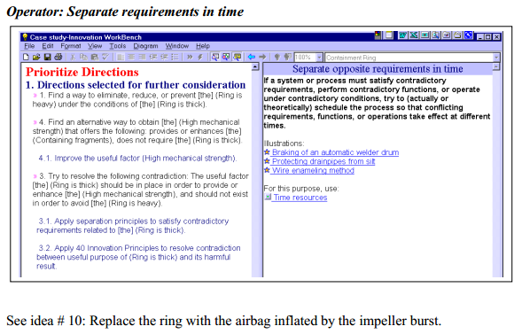
Idea # 10: Replace the ring with an airbag that inflates when the impeller bursts.
Idea # 11. Make a thin ring that has reinforcing ribs. If the ribs are placed on the internal surface of the ring, flying fragments will lose much of their energy smashing into the ribs.
Idea # 12: Make the ring corrugated in two planes.
Idea # 13: Determine where the ring usually breaks and reinforce those places. Idea # 14: Internal ribs with sharp edges can counteract flying fragments, breaking them
into smaller pieces.
Idea # 15: Use a multi-layer ring: additional strengthening rings, rings having different hardness and elasticity, rings which have a gap in between them, filling the gap with an energy-absorbing material.
Idea # 16: Make the ring out of separate layers so that if cracks develop inside they will not spread.
Idea # 17: Use metal-concrete or some other composite material. Idea # 18: Create inner stresses inside the ring: This can be done using wiring, banding, double ring structure, etc.
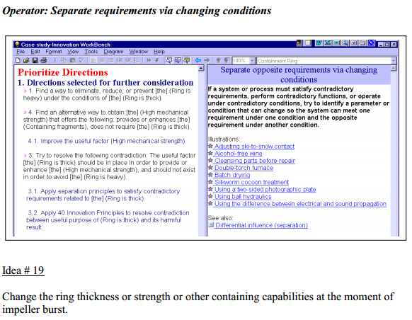
Idea # 19. Change the ring thickness or strength or other containment capabilities the moment the impeller bursts.
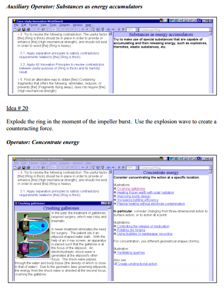
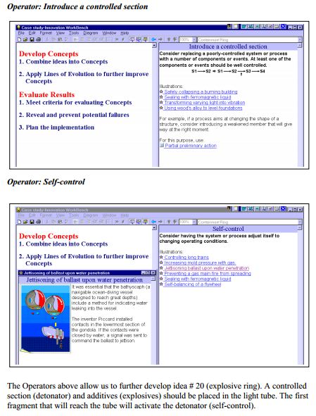
Idea # 20. Explode the ring the moment the impeller bursts. Use the explosion wave to create a counteracting force.
Idea # 21. Disintegrate the fragments.
Idea # 22. Utilize special geometrical shapes to create traps for the fragments. For example, make the ring in the form of spring.
Idea # 23. Create a combination of pressurized air and liquid to counteract the fragments.
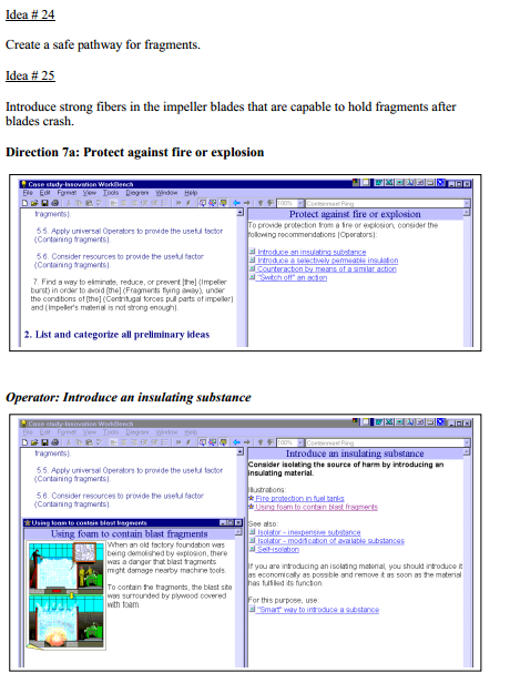
Idea # 24: Create a safe pathway for the fragments.
Idea # 25. Introduce strong fibers in the impeller blades that are capable of holding the fragments after the impeller bursts.
Idea # 26. Use foam or foam-like material to absorb energy. Apparently, we need a special type of foam such as metal foam. We can also consider other fillings that can absorb energy (see idea # 3). Idea # 27. Define the least dangerous directions and redirect the fragments in these directions.
Idea # 28. Distribute the harmful energy between more of the fragments (see also ideas # 7 and 21: reducing energy/mass of the fragments).
Idea # 29. Create a special pathway (spiral) to trap the fragments and to reduce their energy while traveling through the spiral route (see ideas # 22 and 24). Also, see idea # 26: absorb the energy.
Idea # 30. Disposable ring – consider that the ring will be destroyed while absorbing all the energy of the fragments (similar to idea # 3).
Idea # 31. Consider various types of support while transporting the ring.
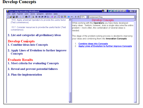
Idea # 32. Learn the details of the transporting process and look for the ways to reduce the number of liftings. We can categorized the obtained ideas into the following groups:
1. Strengthening the ring via
a) changing the ring material structure:
• creating inner stresses (wiring, banding, press-fit) (#18, 7)
• introducing special reinforcing threads (fibers), using metal-concrete or other composite materials (# 9, 17, 25)
• special thermal treatment for hardening the ring material (# 8)
• using a multi-layer ring with layers with different properties (elasticity, hardness, gaps filled with energy-absorbing materials) (# 15)
b) changing the ring’s shape:
• vary the ring thickness to best accommodate the situation (# 6,13)
• create various reinforcing ribs (# 11)
• use two-plane corrugations (# 12)
2. Increasing the ring’s energy-absorbing properties via
a) changing the material structure:
• using foam and/or foam-like materials (metal foam, honeycomb, wiring, brushes) (#3, 23, 26, 30)
• using a multi-layer ring with layers capable of moving relative to one another to absorb extra energy
b) changing the ring’s shape:
• spiral or other traps that can slow down the fragments (#22)
3. Reducing the mass/energy of the flying fragments to reduce damage and allow the ring’s mechanical strength to be lowered via
• changing the ring’s material structure to make it capable of breaking into smaller pieces (# 5, 21,28)
• introduce ribs with sharp edges capable of breaking fragments into smaller pieces (# 11,14)
4. Improve testing convenience, including:
• perform the test without removing the ring (# 4)
• make the ring dismountable and transport parts of the ring rather than the whole thing (# 1)
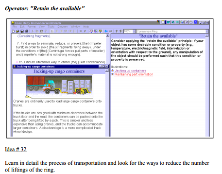
• consider various types of special support during ring transport (# 31) 5. Strengthen the impeller blades to eliminate the need for the ring (#25)
6. Define or create a safe pathway for the fragments (# 24, 27, 29)
7. Change the principle of operation of the ring, including: • replace the ring with an airbag that inflates the moment the impeller bursts (# 10) or change its thickness (# 19)
• explode the ring to create a counteracting force (# 20) and/or break the fragments into smaller pieces
8. Replace the impeller with a safer method of providing air (# 2)
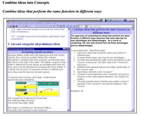
Step 1. Select two ideas that resolve the same sub-problem in different ways.
Idea # 17 (Use metal concrete or other composite materials) and idea # 11 (make a thin ring with reinforcing ribs) provide the same function (strengthening) in different ways – changing structure (#17) and changing shape (# 11).
Step 2. Compare these ideas; each has its own advantages.
Idea # 11 is preferable from the main function point of view because it can provide greater strength. However, it is not easy to make ribs from the steel. The advantage of
idea # 17 is that composite materials are easy to shape.
Step 3. Consider the idea that has better functional features as the “source of resources”; the other idea is the “recipient of resources.”
We select idea # 11 as the “source of resources”
Idea # 17 is the “recipient of resources” Step 4. Determine the elements that provide better functionality of the “source” idea. The element providing better functionality is a steel tube.
Steps 5-7. Apply these elements to the “recipient.”
We can combine two ideas having a steel tube with ribs made from a composite material.


