Application of Crawler Effect in Construction
Editor | On 10, Dec 2005
By: Abram Teplitskiy, Roustem Kourmaev
Abram Teplitskiy, Ph.D., Scientific Consultant
Roustem Kourmaev, President
Advanced Technologies International, Inc., Richardson, TX
tepl@sbcglobal.net
We continue to discuss applications of TRIZ for problem solving in construction, and now came time for caterpillar (crawler) effect. This effect took its origin from the group of biological effects, and is applied in crawler chassis for powerful construction, agricultural and military machines, in areas where quality highways are not made yet.
Having better contact with soils in such, we can say, “not-roads†crawler chassis provides opportunity for different technological machines to operate, and consequently, to do the job. In Fig.1 we can see a general; structure of a simple Crawler Chassis based machine.

Simple crawler based machine for agricultural applications, shown in Fig.1, contains loading area above the rear axle assembly, a driver’s cabin between front axle and rear axle assembly, an engine within the front area of the vehicle and a front frame associated to the front axle assembly as well a rear frame associated to the rear axle assembly is structured in such a manner that the rear axle assembly is provided with a traveling mechanism or alternatively a crawler unit preferably a crawler belt unit, with low loading area and with a swinging axle; the front axle assembly is provided with single tires or with a traveling mechanism respectively. a crawler belt unit, the frame of the crawler belt unit associated to the rear axle assembly is available to its full length and width for net superstructures of the machine, the length of the crawler belt unit and the supporting crawler belts is larger than the width of the crawler unit, the diameter of the guide rollers of the crawler belt unit is substantially smaller than the diameter of the front wheel tires for obtaining a center of gravity as low as possible for the superstructures, and the cabin is positioned between the front axle and the front end of the rear axle assembly. Because of the length of a crawler the contacting area between the chassis and soil is much more bigger than between tires of automobile and asphalt covered highway.
But if the driving conditions are more complicated then even in the agricultural field? How to drive, for example, throughout a marsh? Crawler can help even in such hard “driving’ conditions. One of the possible solutions for this case is shown in the Fig.2.
On the ends of the crawler empty hermetical thrusts are placed, and in a big part they reduce average crawler’s pressure on the marsh surface, which has low bearing capacity. And another trick, applied in this patent – interchanging units with high and low heights on the tracks. Due to these tricks, crawler can tow heavy-duty loads through marsh surface.
Below there are shown a general look of a regular bulldozer (Fig. 3a) and its “crawler chassis†(Fig.3b).
A crawler-type vehicle undercarriage including a track frame, an idler, a sprocket, a crawler encompassing the idler, track rollers, and the sprocket and the idler, the sprocket and the track frame located to line up in a straight line comprising the crawler-type vehicle undercarriage comprising (i) an idler avoided from pivoting upwardly or downwardly relative to the track frame, (ii) a first arm pivotally mounted at the bottom of the track frame, and (iii) a second arm pivotally connected to end portion of the first arm. The track roller unit adjacent the sprocket is preferably pivoted about a pivot center of the first arm positioned at the bottom of the track frame and toward the idler relative to a pivot center of the second arm. The track roller travel improves a flexibility of the track roller to the crawler, and work in a high tractive force is carried out with the track rollers providing unchangeable real contact areas to the ground. Crawler can also do additional jobs, besides driving-only job. In Fig.4 readers could see a crawler-based attachment for a track, which facilitates loading operations.
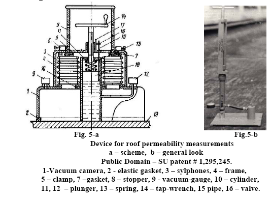
Now let’s discuss some technologies, which are using crawler principle of operation, but when crawler units are resting. These technologies were developed under direction of authors of this article. First technology was devoted to continuous testing construction materials permeability (1). The basic idea was proposed in SU Patent #1,295,245, and is illustrated in Fig. 5.
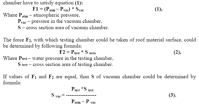
Device for permeability measurements is placed on the testing surface by action of a vacuum cup. Air from chamber 2 is pumped out using silphon based or other portable pump. For this purpose cross-section areas of vacuum chamber and water pressure

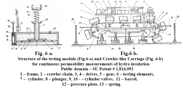
After getting practical experience in testing permeability of mostly horizontal roofs, we got an idea of continuous testing permeability of any type of hydro-insulation works, including hydro-insulation of reservoirs and other similar structures, where it is often necessary to provide testing on inclining and even vertical surfaces and where it would be desirable to provide control using a crawler type of carriage (2). The general look of the developed device is shown in Fig. 6.
Device for continuous measurements of hydro-insulation is based on crawler carriage, which contains a loop of chain elements with two drives, and gearing. Pressure elements (Fig.6a) are connected through pre-calculated distance depending of the project features. For testing pressure elements are filled with water; and complete device is installed on testing surface of the structure. After the machine is turned on, due to the crawler principle the machine would stay in testing place pre-determined time. After testing the first place would be complete, the water would be pumped out of the chamber, and crawler could move the device in the next testing position. Details of testing procedures could be found in the patent materials.
We also would like to discuss application of crawler principle to soil compaction quality control. Technical contradictions in soil compaction are as follows – the machine for soil compaction is working continuously, but quality control testing is providing selectively. To solve this contradiction, we proposed two ways to synchronize both of these processes – soil compaction and testing. First idea is illustrated by picture in the Fig. 7.
The algorithm of work of above shown device is as follows. The spherical probe along with compaction machine “participated†in the compaction step-by-step process. Wheels 13 of the testing apparatus are rolling over the soil surface. While the wheels are moving over the soil surface, the “crawler†catenary’s gear moves the weight 4 on the top of the bar 8. When weight 4 would get to the top position on the bar 8, the catchers 11 opens, and weight 11 fall down and impact the testing sphere 1. The sensors of the depth, on which the sphere 1 penetrated in the soil, could be graduated in units of density. The results of each testing could be automatically displayed on the monitor at the machinist panel. Described device could be installed on any compaction equipment. In the Fig.9 is shown such device installed on the soil compaction roller.
Now let’s consider step-by-step testing technology, which are close to crawler principle, and hopefully could help solve some other problems in construction. For realizing the step-by-step principle it is necessary an algorithm of probe movement relatively the carriage, when on the first step probe moves together with the carriage, on the second step – the probe should stop for providing testing operations, and on the third step – probe would catch up the carriage, and returns in starting position. The general scheme of such step-by-step equipment developed by authors is shown in the Fig. 9 (3).
Step-by-step testing probe contains a carriage and testing probe by itself, which is illustrated in Fig.9. Testing probe is attached to the front axle of the carriage with flexible stay bars. To the axle is fastened a main drive of roller-sleeve chain gear, which drives probe in vertical direction. Also on the front axle another main drive is fastened, which has a lug and is conjugate with above-mentioned chain for moving testing probe in horizontal direction. In the middle part of last chain an electromagnet is conjugate with it by its plunger. The second drive is freely rotating on the back axle of the carriage. During the carriage movement the lug of main drive pushes end switch, and as a result close the electrical chain of the electromagnet. Plunger of the electromagnet engages with upper branch of roller-sleeve chain. As a result the probe block started to move in direction of the carriage movement with velocity, which is in 1.5 times bigger than velocity of the carriage. After end of lug action, the electromagnet is switched off, and testing probe is stopped relatively the surface of the testing area of the soil. In the moment of electromagnet is switched off, a time relay is on along with testing probe and Electromagnet. The plunger of an electromagnet moves inside, and weight moved in a position to hit the probe. As a result the cone end of the probe is plunged in the soil on specific depth Depending of soil’s density. While the probe is plunged in the soil, a variable resistor is rotated, and its resistance could be indicated by suitable electrical gauge.
We’ll finalize this article with application of crawler effect for testing pipes. A version of element-by-element testing is shown in Fig. 10. It is, developed under guidance of authors of present paper, a self-moving testing module (Remember principle of “selfservice�).
Testing device contains a moving trolley 1 with chassis 2, way rollers 3 and driving gear 4, which are connected by chain 5 with chassis 2. Placed on the trolley 1 frame 6 with lodgments 7, contains rubber coreless gaskets 8, which are made from elastic material and filled with a fluid 9. Tank 10 for supplying liquid is connected with balloon 11 with compressed air, and systems of electro supply and remote control. Testing device also contains spring-loaded pushing rings 12 for rubber coreless gaskets 8. Screws 13 through springs 14 manage the strength of this pushing. Being attentive, readers could notice that coreless rubber gasket in above example works as crawler, one part of which is moving while another part is “stayingâ€.
Installing pipes by element-by-element testing technology could be realized as follows. Testing module is inserted in pipe 20. Capacity 10 and space 18 are filled with liquid. Using remote control system, driving gear 4 and balloon 11 with compressed air are switched on. The compressed gas from balloon 11 entered space 18. Pushing rings 12 under pressure of spring 14 provide contact pressure necessary for compress coreless rubber gaskets 8 between the internal surface of the pipe and lodgments. Testing module is moving inside and lengthwise the pipe. Due to the high friction between internal concrete surface of pipeline and rubber gaskets 8, gaskets are slipping along the lodgments 7, and as result they are not sliding, but are rolling over the pipe. Due to the springs 14, very effective compression of gaskets is provided during all time of operating of the equipment. Possible loosing of a liquid from testing space 18 due to the leaks in pipe joints are compensated by displacement of a liquid from capacity 10 by compressed gas from balloon 11.
1. Abram Teplitskiy et al., Device for Testing Permeability of Hydro-Insulation, SU Patent # 1,295,245.
2. Abram Teplitskiy et al., Equipment for Testing the Quality of Hydro-Insulation, SU Patent # 1,816,992.
3. Abram Teplitskiy, Technology of Soil Compaction Quality Control, Kiev, Publishing House Budivelnik, 1985, 73 pages (In Russian).
4. Roustem Kourmaev, Abram Teplitskiy, Application of Inventing Problem-Solving Theory (TRIZ) In Pipeline Technologies, Proceedings of International Conference in Pipelines, Baltimore, Maryland, 2004.
5. Abram Teplitskiy, Roustem Kourmaev, Solving Technical Contradictions in Construction with Examples, TRIZ Journal, July 2005
6. Abram Teplitskiy et al., Equipment for testing the Density of Cement-Soil Mixtures During formation of Antifiltration Cut-off Walls, SU Patent #1,079,978


