
Thermal Deformations in Engineering

Editor | On 08, Aug 2006
By: Alexander Kynin, Seunglhee Suh, Seungheon Han
Alexander Kynin a.kynine@samsung.com, Seunglhee Suh, Seungheon Han
SAMSUNG Electro-Mechanics Co. Ltd., South Korea.
The most part of the materials changes its volume under the influence of temperature.
Accordingly, the part of the system, which made from these materials, changes the sizes. This effect can be harmful, in the case of appearance in the construction of thermal stresses, and useful, with its use in different devices. In TRIZ to a change in the sizes of objects under the thermal influences is given considerable attention and it is introduced as the separate principle (?: USES OF THERMAL EXPANSION). At the same time, in the published works was impossible to find the analysis of the processes, which was connected with the thermal changes sizes of the objects. The purpose of the work is: the generalization of available data on averting of thermal deformations and on the use of size changes under the thermal influences in the technology; the analysis of these data with the use of tools TRIZ (principles, Contradictions, Substance-Field analysis) and their classification; the determination of the promising tendencies in the given regions in accordance with the laws of the development of technical systems; the illustration of the application of TRIZ for describing the effects, the connected with the changes sizes of the parts of the systems under the thermal influences. The proposed work is intended for the aid to inventors in the selection of the most effective methods of the solution of production problems, and also to the instructors of TRIZ for to use in their work of the represented examples.
THE REASON FOR THE THERMAL DEFORMATIONS
In the work of engineer it is necessary to consider a change in the sizes of objects under the thermal influences. This is connected with the fact, which the environment temperature changes and with this synchronously changes sizes the objects surrounding us; moreover, depending on the material used, they make this differently. Accordingly, in the places of contacts those stretching appear, or the compressive stresses, change dimensions of details and distance between them etc. The purpose of the work is the analysis of the possible methods of fight with the thermal deformations and the application of size change under the thermal influences, and also the comparison of these methods with the actually existing technical solutions. In this work only thermal changes in the sizes of materials will be examined, not connected with a change in their phase state.
Changes in the volume of substances with a change in the temperature
The thermal motion changes the distance between the molecules. As the temperature changes, the thermal vibrations of the molecules in a solid body become anharmonic relative to their equilibrium positions. As the temperature rises, the intensity of the thermal motion of the molecules increases. The equilibrium distance between neighboring particles increases. Thus, the length of the body increases. As the temperature falls, the equilibrium distance between neighboring particles decreases.
This phenomenon is characteristic for the substances, being been in any phase state; moreover it is most noticeable for the gases. Some artificially created materials are exception, the having zero or negative thermal-expansion coefficients.
Terms and definitions
The thermal deformations of materials it is determined by the value of their coefficients of the linear thermal expansion (CLTE). CLTE – this is the relative elongation of model with a change in the temperature to 1?. The thermal expansion coefficient, a, depends on the temperature range. The volumetric thermal expansion coefficient, ß, is approximately equal to 3a. The body temperature must be below its melting point / 1 /.
PREVENTING THE THERMAL DEFORMATIONS
With the purpose it is sufficient representative examination of the technical solutions, the connected with the thermal changes sizes was analyzed basic literature on TRIZ, the base of the effects of program TechOptimuzerâ„¢ and the patent base USPTO.
Model of the process
Let us model situation in general form. Us will interest only thermal a change in the sizes of details, finding in the contact with other parts of technical system. The model of the system in question is certain tool, which is found in the mechanical contact with the work piece (article). Tool and article can consist as of different, so from the identical materials. Furthermore, let us exclude from the examination a change in the temperature of article, caused by contact with the tool. I.e., we will consider article object, not changing its sizes under the action of mechanical, or temperature actions. With a change in the temperature of tool its sizes change. For simplicity of model we will examine in only change in its linear dimensions. In this case in the article appears additional mechanical stress (compression, or expansion), which attempts to cause the displacement of article. Our purpose is a decrease, or the complete liquidation of stresses in the article, the caused by change dimensions of tool.
In this case the formulation of the problem does not present complexity and it is possible not to use ARIZ. Furthermore, since we examine technical system – substance, that to formulate Technical Contradiction (TC) is not compulsory and can be passed to the determination of Physical Contradiction (PhC).
Ideal Final Result
Let us formulate IFR. For our case it will consist in that, that the tool ITSELF will not change its sizes. I.e., the tool must have zero CLTE. In this case this is possible. Materials, having zero CLTE, they are known.
EXAMPLE 1: Researchers in the US have discovered a metallic alloy that does not expand or contract when heated and also conducts electricity at the same time. The material could have applications in components that encounter large temperature fluctuations, such as motors and actuators, and also in space.
Obtaining materials with small or zero CLTE
Obtaining materials with zero CLTE is fairly complicated problem. The fact is that for the compensation of thermal expansion of crystal lattice is necessary or its reformation with the decrease of the interatomic distances (similar to reconstruction of the structure of alloys with the “memory of form”, or the interpenetration of crystal lattices of different components of material. Materials with the zero are known, or small, CLTE:
– Invar and other alloys
– Ceramic materials on the basis of glass and oxides
– Polymeric materials.
Physical contradictions
We can formulate the following contradiction: Tool from the utilized material must be large, because with the heating its size increased and tool must be small, in order not to cause the appearance of secondary stresses. We cannot divide tools requirement in the time, or to change its physical chemistry parameters, but we can divide requirements in the space, or to use system passages. For the separation contradictory requirements in the space can be used the following methods: splitting; carrying out; local quality; asymmetry; nesting; passage into another measurement; mediator; copying; flexible shells and thin films and the application of porous materials. The solution OF PhC in this case they can be following:
The internal volume of tool can be executed in the form of porous construction.
EXAMPLE 2: A multicellular monolithic ceramic body having many gas passages partitioned by thin walls is made of aluminum titanate as a major constituent and has less than 0.15% of a thermal expansion coefficient at 1000? and higher than 350 kg/cm2 of a compressive strength as zero of an open frontal area as the properties in the direction along the gas passages and more than 35% of a porosity /2/.
For the circuit of contradictory requirements due to the system passage the following passages can be used: in the super-system; in the subsystem; to the anti-system or to the combination with the anti-system; to the system, parts of which have properties of anti-system or to forego the system. Passage into the anti-system or to the combination with the anti-system: – to compensate harmful effect by opposite action.
For this into the material with positive CLTE it is possible to introduce material with negative CLTE. This solution also corresponds to direction “passage into the subsystem and to the micro-level – to use composite materials”. These additives can be, for example, they are introduced in the form of particles.
EXAMPLE 3: A ceramic article which consists essentially, by weight on the oxide basis, of 10-25% SiO2, 65-85% Al2O3, and 2-12% Li2O and comprises beta-eucryptite as a first phase having a negative component in thermal expansion and a melting point Tm1, and a second phase having a positive component in thermal expansion which is higher than the component in thermal expansion of the first phase and a melting point Tm2, wherein Tm2>Tm1, wherein the first phase is at most 50% by weight of the ceramic, and wherein the ceramic is characterized by microcracking. Tm2 is at least 1800?. The ceramic article exhibits a near zero coefficient of thermal expansion from room temperature to 800?, a high refractoriness, and a high resistance to thermal shock properties which make the inventive ceramic extremely desirable in high temperature applications, such as filters for diesel exhaust engines /3/.
Obtaining composites is the more extended case, containing fibers. Composites frequently are used, the containing carbon fibers, which possess small CLTE in the axial direction.
EXAMPLE 4: Improved fiber reinforced composites having near zero coefficients of thermal expansion are described. The improved composites include reinforcing fibers and matrix material in which gap structures which exist within the composite are filled with a bonding agent. The reinforcing fibers can be unidirectionally, bidirectionally or multidirectionally oriented within the matrix material and articles fabricated from the improved composite have reduced coefficients of thermal expansion in directions transverse to the orientations of the fibers. This improvement makes these improved composites useful for fabricating high energy laser mirror substrates /4/.
Materials with negative CLTE
Such materials are encountered among:
– alloys;
– ceramics on basis of ZrW2O8 and ZrP2O7 and other oxides,
– ceramics on the basis of phosphates;
– ceramics on basis of zirconium molybdate and hafnium molybdate
– the polymers
– and also different composites.
The uncommon version of the use of composites for obtaining the materials with negative CLRE is obtaining the iron-nickel metal-oxides:
EXAMPLE 5: Negative thermal expansion artificial material from iron-nickel alloys by oxide coextrusion with reductive sintering. Objects with a fine-scale design of bimetallic beams can display negative thermal expansion. Based on a unit cell design for a negative expansion, produced by Optimal Design methods, we fabricate a thermoelastic «artificial material» using coextrusion of iron and nickel oxides, followed by reductive sintering. A bulk sample with 162 unit cells from Fe-60Ni and Fe-36Ni alloys displayed a thermal expansion coefficient of –3.0 × 10⁻⁶/°C, in agreement with the optimal design prediction. [ 5 ] ; Artificial Material with negative thermal expansion coefficient. Constituents: Ni-Fe alloys. Unit size: 600 µm. Smallest feature: 60 µm. Predicted CTE=-3.2 (µ/ °C). Microfabrication by coextrusion and reductive sintering- ONR / 6/.
Sometimes it is possible to limit to small decrease CLTE in the material. This illustrates approach “step back from the IFR”. In this case for compensating the thermal expansion it is possible to introduce substance with the small into the material, or by zero CLTE:
EXAMPLE 6: The deformation of polymer they descend by the introduction into it of highly dispersed filler with small CLTE. Thus, during the introduction into 100 weights. h. epoxy resin 250 weights part quartz sand CLTE of composition it decreases 2 / 7 /.
Conclusions within the part PREVENTING THE THERMAL DEFORMATIONS
Patents are analyzed, connected with the creation of materials with the small, or by zero CLTE. For their obtaining the following principles can be used: local quality; asymmetry; passage into another measurement; flexible shells and thin films and the application of porous materials. Furthermore, the method of obtaining the composite materials is widely represented, into which are introduced the materials with negative CLTE.
OPPOSITION TO THE THERMAL DEFORMATIONS
It is possible to avoid undesirable phenomena, accompanying a change in the sizes of the elements of technical system with a change in the temperature, if we change its construction. Examples, illustrating fight with the stresses, by the caused thermal deformations in Altschuller’s books they were not discovered. With some reservations the method of the protection of pipes during the freezing can serve as an example of fight with the thermal deformations. However, this example is connected with volume change with the phase transition.
EXAMPLE 7: For the protection of pipes from break during the freezing in the pipe they place the pneumatic plastic insert (hose). Freezing, water is enlarged and squeezes soft insert, and pipe remains whole.
In the base of data of program TechOptimuzerâ„¢ the following examples of the technical solutions are represented:
EXAMPLE 8: Matched thermal expansion support system – The crystal supports thermally expand and contract to maintain the position of the crystal /8/.
EXAMPLE 9: Temperature stabilizes path length difference – The temperature expansion of the mirror stabilizes the path length difference of the interferometer / 9/.
EXAMPLE 10: Adjusting position of working head of machine – Thermal deformation of the base changes the relative position of the working head and the table / 10/. Ideal Final Result
Let us formulate IFR. For this case it will consist in that, that the tool ITSELF will not change its sizes. I.e., tool must be made from the material with zero CLTE. Materials, having zero CLTE, they are represented into in the part: The obtaining of materials with small or zero CLTE.
Physical Contradictions
In the situation in question we have contradictory tools requirement. Physical contradiction was formulated in the division PREVENTING THE THERMAL DEFORMATIONS. We cannot divide tools requirement in the time, or to change its physical chemistry parameters, but we can divide requirements in the space, or to use system passages.
For the separation contradictory requirements in the space can be used the following methods: splitting; carrying out; local quality; asymmetry; nesting; passage into another measurement; mediator; copying; flexible shells and thin films and the application of porous materials: – to separate the Tool, thus, so that its parts would have the capability of displacement relative to each other.
EXAMPLE 11: Some descent vehicles had heat shield in the form of fish-scales; bridges and rails do not make with continuous, and they divide into parts, divided by the expansion joints. – to pass into another measurement and to make an object asymmetric, in order due to the local quality of the remote part of the tool to compensate for the appearing stresses.
EXAMPLE 12: Into the conduits are introduced loop and Z- compensators (compensator – this is device, making it possible to receive the linear expansions of conduit from a change in the temperature of pipe); – – to introduce mediator, which due to the flexible shell can compensate the appearing stresses.
EXAMPLE 13: Lens expansion joints and Axial expansion joints; – to introduce mediator, this will have CLTE average, than in two mating parts of the system. In this case the stresses between the parts of system will be lowered. Such solutions frequently are used in the semiconductor production, where inter-layers are introduced.
EXAMPLE 14: Compensation of Internal Thermal Stresses in InGaAsPAnP Lasers. – to separate the object to two parts and to put one part into the part with the large diameter according to the type of nesting. Into junction of parts to introduce stuffing the box.
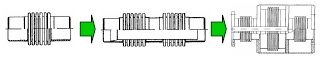
EXAMPLE 15: Compensators are stuffing box;
EXAMPLE 16: Cathodic device of aluminum electrolyzer. Brick lining is made subdivided with the arrangement between its sections interlayers from the compressible material, in this case in the places of the adjoining of brick lining to the cathodic rods the layer of material is located, ensuring sliding of cathodic rods and brick lining relative to each other and compensation for their thermal expansion /11/; – to introduce between the object and the subject padding (mediator) from the porous material.
EXAMPLE 17: the rubber packing between the roofing polycarbonate sheets “presses” the edge of sheet, possibility for the thermal expansion leaves in this case; For the circuit of contradictory requirements due to the system passage the following passages can be used: in the super-system; in the subsystem; to the anti-system or to the combination with the anti-system; to the system, parts of which have properties of anti-system or to forego the system. Passage into the supersystem: – to convert the harm of expansion in benefit due to the association of the parts of the system from the uniform materials with identical CLTE and agreement of components.
EXAMPLE 18: Device for compensating the thermal expansions of microprobe for the scanning probe microscopy;
Passage into the subsystem and to the micro-level:
– to separate the system (see EXAMPLE 11).
– to use the composite materials (see EXAMPLE 3).
Passage into the anti-system or to the combination with the anti-system:
– to compensate harmful effect by opposite action. For compensating the deformation of object it is possible to use material with negative CLTE.
EXAMPLE 19: The enhancement in temperature sensitivity of wavelength (for a given package length) in this design arises from the use of a unique metallic alloy with a negative coefficient of thermal expansion (CTE). One end of the FBG is bonded to a negative CTE ( a
1 = 20*10-6?) Ti–Ni
alloy with a length of 6.99 cm, the other end, to a positive CTE ( a
2 = +22*10-6?) aluminum alloy
with a length of 11.43 cm. When it is heated, the negative CTE component contracts, whereas the positive CTE component expands, thereby inducing a superimposed temperature-dependent tensile strain in the FBG, resulting in a wavelength shift that is programmable by temperature /12/. It is possible to compensate harmful effect by the introduction of external element, for example to introduce into the system element, which prevents deformation. This is possible, if the material of this element (holder) has smaller CLTE, than the material of the tool:
EXAMPLE 20: Adhesive leakage prevention – Thermal expansion of the ceramic blanks and frame prevents adhesive leakage/ 13/.
Standards and the laws of the development
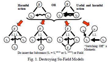
If entire problem is concentrated around interaction of two objects, that this situation can be examined, as Substance-Field (Su-Field) model. In the system in question article will be the detail from the material, possessing the thermal coefficient of deformation. Under the initial conditions the article interacts with the tool. Their interaction is ensured due to mechanical interaction (fields), but this interaction is not harmful, since the contact between the parts of system necessary for the work ensures. With a change in the ambient temperature the tool changes its sizes and additional harmful stress appears between it and article. I.e., as a result of drawing of model is obtained Su-Field with the useful and spurious couplings. The use of standards of sub-class 1.2 is the possible solution of this situation. Destruction by the Su-Field: the elimination of spurious coupling by introduction S3; the elimination of spurious coupling by the introduction of those altered S1′ and (or) S2′; the “drawing out” of harmful action and reaction to spurious couplings with the aid of F2:
However, from a practical point of view to more conveniently examine standards and laws of development not separately, and under the conditions for their interaction. For this it is possible to use a unit of the predictions of program TechOptimuzerâ„¢. The trend is the first developmental trend: Mono- bi- poly.
EXAMPLE 21: an increase in the quantity of corrugations of axial compensator (see Error! Reference source not found.).
The trend is another developmental trend: Introduction of new substance into component. It corresponds to standards on the elimination of spurious coupling by introduction S3, or altered S1′ and (or) S2′;
– the internal additive. In this case it is possible to use note to standard 1.2.2: Substance S3 can be introduced into the system from without in the finished form or is obtained (by action F1 or F2) from the existing substances. In particular, S3 it can be “void”, by phials, by foam etc. In this case we can supplement the previous example: Introduction of the compressible additive to tool cm. EXAMPLE 7 .
EXAMPLE 22: For the protection of article from thermal deformation in it they place porous insert, which compensates stresses. Insert can be obtained by the frothing of the material of article. Examples it is not found.
– the external additive. Here it is possible to use standard 1.2.4. “opposition to spurious couplings with the aid of F2”, i.e., to introduce into the environment the source of field, which counteracts deformation. To compensate harmful effect is possible by the introduction of external element, which is the source of mechanical field (see EXAMPLE 20) or intensively cooling the part (for example internal) of tool. The same example can be examined, as the introduction of additional field see Fig. 1)
– additive to the environment:
Examples it is not found.
– the additive between Tools and by Article is the very extended method. Introduction of substance, with the intermediate value CLTE are reduced the stresses. This method is analogous to the introduction of the “mediator” (see EXAMPLE 14). The segmentation of space is the following trend.
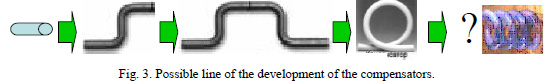
EXAMPLE 23: In this case in the form of porous construction the internal volume of tool can be executed. Many rigid materials in the form of thin films possess flexibility. For example, it is possible to create in the material of the tool of time (see EXAMPLE 2. The segmentation of surface is the following trend. This trend is passage from the smooth pipe to the expansion bellows (see EXAMPLE 13).
Geometric evolution is the last trend examined. This trend is passage from the straight pipe to Z compensators, and further (see EXAMPLE 12). These cases correspond to passage line – plane – volume.
It is possible to assume, that the volumetric constructions (of type of spiral) will be more effective. Naturally, that their production is more complicated, but they can compensate large deformation and they will have small resistance.
Conclusions within the division OPPOSITION TO THE THERMAL DEFORMATIONS
As a result of the analysis of the methods of opposition to thermal stresses the basic trends of their development were revealed. Were found examples of use in the engineering practice of the following tools TRIZ:
– the principles of the solution of PhC: splitting, passage into another measurement, asymmetry, local quality, carrying out, mediator, flexible shells, nesting, porous materials.
– the system passages: harm in favor, the association of the parts of the system, uniform materials, the agreement of components.
– passage into the subsystem and to the micro-level: splitting, composite materials.
– passage to the combination with the anti-system: to compensate harmful effect.
– trend Mono- bi- poly: Introduction of modified substance into component. internal additive is the external additive external additive the additive between tools and by the article
– Segmentation: Segmentation of surface.
– geometric evolution.
USING OF THE THERMAL DEFORMATIONS
Thermal deformations can not only create problems, but also to be useful in a whole series of areas of technology. This is the application of the principle: “to convert harm in benefit”. However, in this case, we cannot limit to the examination only of interacting pair “tool – article”, and to examine the elements of technical system in their interaction. The analysis of examples from literature and patent fund showed, that in the technology size change under the thermal influences they are used for the realization of the following functions: to move article, to deform article, and to regulate the sizes between the parts of system.
TO MOVE THE ARTICLE
Its application for the displacement of the parts of different devices is the most frequent case of using the thermal expansion. To move article linearly
EXAMPLE 24: Device for the micro-transfer of working object, which contains two rods, subjected electro-heating and cooling on the predetermined program and alternately moving object in the necessary direction /14/.
EXAMPLE 25: The thermally expanded sensing element precisely displaces the microscopic stage /15/
EXAMPLE 26: Thermal drive with heat-sensitive material – The expansion of heat-sensitive material moves the liquid and the rod / 16/.
To turn the article
EXAMPLE 27: Heat engine for toys – Thermal expansion and contraction of the belt parts drive the drive shaft /17/.
EXAMPLE 28: Solar energy converter – Elongating temperature-sensitive bars rotate an engine shaft / 18 /.
To turn and to move the article
EXAMPLE 29: Precise translation of object – The elongation of a heated screw translates the object /19/.
TO DEFORM THE ARTICLE
The extended case of using the thermal expansion it is its use for creating the stresses in the system and deformation of the parts of the system:
To press article along one axis
EXAMPLE 30: Extension of temperature range of storage plate – A cooling substrate compresses ferrite microcores to increase the limit operating temperatures / 20/.
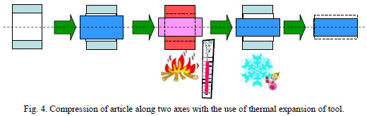
EXAMPLE 31: Joining semi-coils of split inductors – Thermal compression of a tightening device couples the contacts of semi-coils / 21/. To press article along two axes
EXAMPLE 32:Billet for the hot pressing of the concentrically located bushings, prepared from different materials, in each of which the temperature coefficient of linear expansion is higher than the temperature coefficient of the linear expansion of the material of bushing, located inside it / 22 /.
EXAMPLE 33: ???????? ??????? ????? ????? ?????????? ??????? ??????????. Doublewall pipe – The external bush reduces the internal bush during cooling /23 /.
To volumetrically press the article
EXAMPLE 34: Reduction of volume of float by rods – Decreasing the length of rods reduces the volume of the float / 24/.
To extend article along one axis
EXAMPLE 35: An example is not thus far found.
To extend article along two axes
EXAMPLE 36: Thermal expansion of tubes – Increasing the diameter of an instrument through heating expands the tube /25 /
EXAMPLE 37: Abrasive tool fabrication – The thermal expansion of a body presses it against an abrasive ring /26/.

To volumetrically extend the article
EXAMPLE 38: Thermally conductive joining – Heating the joint adhesive with impurities in it makes
a heat conducting joint /27/

The variant of the temporary use of a tool with the sizes is interesting, which changed by thermal influence.
EXAMPLE 39: Method of the wire drawing of pipes on the mobile mount with which, preliminarily heated is introduced in the pipe before the wire drawing, which then easily is extracted / 28 /.
TO DEFORM THE SYSTEM
System can be bent, using two rods with different CLTE. EXAMPLE 40: Micro-gripper – The temperature difference between the beams causes the microgripper to bend /29/.
The application of different temperature-sensitive elements and thermo-regulators on the basis of bimetallic plates is one of the most known examples of the use of thermal deformation. Such plates illustrate passage to the bi- system.
EXAMPLE 41:A bimetallic solid consists of two metal plates fastened together. The coefficient of linear thermal expansion of plate 1 exceeds that of plate 2. Heating the bimetallic solid bends it / 30 /. TO REGULATE CLEARANCES BETWEEN THE PARTS OF THE SYSTEM A change in the distances between the parts of system is very area of importance for applying the thermal changes. For example, changing clearances between the parts of system it is possible to regulate the fluid flows and gases.
EXAMPLE 42: With the displacement of the seizure of robot seizure with the braking presses to the piston, which displaces oil from the camera through the narrow slot. Oil heat after a certain time, its viscosity falls and it is pressed through the slot without the special resistance. Proposed to carry out slot in the form of the been self-governing bi- system with the moved characteristics: slot is formed by two elements with the different thermal-expansion coefficients, which with heating of oil themselves decrease the area of slot and the total resistance it remains constant / 31/.
EXAMPLE 43: Expander shuts fluid off – The thermal expansion of the expander moves the trip rod and shuts off the fluid / 32/.
EXAMPLE 44: Heat-sensitive capillary regulates gas dosing / 33/.
EXAMPLE 45: Refrigeration system energy efficiency increase – Changing the volume of the refrigerator thermal expansion device increases the energy efficiency / 34/.
EXAMPLE 46: Rod overlaps gas flow as temperature increases – The rod overlaps the gas flow when the temperature increases / 35/.
Changing clearances between the parts of system it is possible to also regulate clearance between the shaft and the packing ring.
EXAMPLE 47: Ring reduces pressure of seal on shaft – A ring with a high thermal expansion coefficient reduces the seal pressure of the shaft / 36/.
Conclusions within the division THE USING OF THE THERMAL DEFORMATIONS
The analysis of the examples examined showed, that in the technology size change under the thermal influences they are used for the realization of the following functions: to move article (is linear, to turn and to move article), to deform article (to enlarge and or to press on one, two, or to three axes), to deform system and to regulate the sizes between the parts of system.
GENERAL CONCLUSIONS:
Proposed article examines basic aspects, connected with a change in the sizes of the parts of different technical systems with the change temperatures. Basic problems are revealed, connected with the thermal changes and the region of their application. The systematization of all possible methods of averting is produced, fight or the use of thermal changes, used in this stage of development of technology.
It is shown, that the development of these methods corresponds to the basic trends of the development of technical systems.
REFERENCES
1 Askeland, Donald R. The Science and Engineering of Materials. Boston: PWS Publishing Company, 1994.
2 US Patent. 4327188.
3 US Patent. 6566290, US Patent. 2002004233.
4 US Patent. 5382309.
5 Journal of Materials Science Issue: Volume 39, Number 13 Date: July 2004 Pages: 4113 – 4118
6 http://msewww.engin.umich.edu/research/highlights/neg_therm_exp
7 US Patent. 5714537; Laughner, Michael K., et al.; Feb. 3, 1998; “Filled carbonate polymer blend compositions”; The Dow Chemical Company.
8 US Patent. 5488832; Gallagher; Feb. 6, 1996; “Matched thermal expansion support systemâ€; Philips Electronics North America Corp.
9 Thuiller ,G., and Gordon G. Shephend. “Fully Compensated Michelson Interferometer of Fixed-Path Differenceâ€; Applied Optics 24, no. 11 (1985): 1599?1603
10 SU Patent 189,281; Pronikov; Sep. 17, 1966; “Method of automatic adjustment of working organs of machine-tools.â€
11 SU Patent 97107199/02
12 http://msewww.engin.umich.edu/research/highlights/neg_therm_exp
13 US Patent. 5555798; Miyashita, Akimi, et al.; Sept. 17 1996; “Hot press for producing a multilayered substrateâ€; Hitachi Techno Engineering Co., Ltd.
14 SU Patent. 242127
15 SU Patent. 259612
16 SU Patent. 476458;
17 SU Patent. 336421;
18 SU Patent. 969956;
19 SU Patent. 424438;
20 SU Patent. 266853;
21 SU Patent. 711707;
22 SU Patent. 312642
23 SU Patent. 312642;
24 SU Patent. 411306;
25 SU Patent. 647041;
26 SU Patent. 236279;
27 US. Patent. 5554240;
28 SU Patent. 309758
29 Pan, C., and W. Hsu. “An Electro-Thermally and Laterally Driven Polysilicon Microactuator.”
Journal of Micromechanics and Microengineering 7, no. 1 (1997): 7?13.
30 Landau, L.D., and E.M.Lifshitz. Course of Theoretical Physics. Vol. 1. Mechanics. Oxford,
England: Pergamon Press, 1969., Shames, Irving H. Engineering Mechanics. Statics and Dynamics.
Englewood Cliffs, New Jersey: Prentice Hall, 1997
31 US Patent. 3791494.
32 US Patent. 3784,095;
33 SU Patent. 476450;
34 US Patent. 5546757;
35 US Patent. 4354482;
36 US Patent. 5217232;